

Wheel type crane and centre revolving joint thereof
A center rotary joint, rotary body technology, applied in the direction of connection, rotary current collector, current collector, etc., can solve the problem of difficult processing of rotary body, to ensure work reliability and safety, improve sealing effect, prevent leakage flow effect
- Summary
- Abstract
- Description
- Claims
- Application Information
AI Technical Summary
Problems solved by technology
Method used
Image

Examples
Embodiment Construction
[0034] The core of the present invention is to provide a central rotary joint. By setting the rotary body of the central rotary joint separately, and then splicing them into a rotary body that meets the size requirements of the long central rotary joint through segmental processing of ordinary machine tools, the weight of the rotary body is reduced. Processing difficulty, thereby reducing the overall manufacturing cost of the central rotary joint and shortening its manufacturing cost. On this basis, the present invention also provides a wheeled crane including the above-mentioned central swivel joint.
[0035] Without loss of generality, the first specific embodiment of the central swivel joint provided by the present invention will now be described with reference to the accompanying drawings.
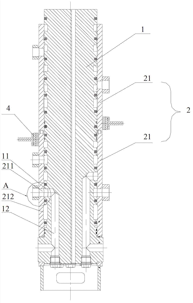
[0036] See image 3 , Figure 4 and Figure 5 ,in, image 3 A schematic structural view of the first specific embodiment of the central rotary joint provided by the present inventi...
PUM
 Abstract
Description
Claims
Application Information