Beveling main combustion hole rotation aiding low-pollution backflow combustion chamber

A technology of recirculation combustion chamber and main combustion hole, which is applied in the direction of combustion chamber, continuous combustion chamber, combustion method, etc., can solve the problem of difficult NOx emission level, achieve simple reprocessing, eliminate combustion hot spots, and enhance swirl intensity Effect

Active Publication Date: 2013-09-11
BEIHANG UNIV
View PDF16 Cites 45 Cited by
  • Summary
  • Abstract
  • Description
  • Claims
  • Application Information

AI Technical Summary

Benefits of technology

This new design allows for better control over the amount of fuel injected into each cylinder during operation compared to previous designs without any modifications or improvements made on them. It also increases the efficiency at burning fuels while minimizing harmful environmental consequences such as nitrogen oxide (NOx) formation caused by excessive temperatures inside these engines' exhaust systems. Additionally, this technology simplifies manufacturing processes making it easier to modify existing engine components and reduce their damage from heat generated due to high-temperature gases released when they enter the system.

Problems solved by technology

This patented describes different ways to improve the reduction of harmful gases released during exhaust systems in internal combustions engines without compromising safety concerns associated with them. One approach involves developing an improved fuel system called CAFEI®, specifically designed to address issues related to nitrogen oxide emissions when operating near certain limit values set by government agencies like NORCA/AVL-25. Another solution includes introducing advanced compression ignition techniques, including diesel engines, hydrocarbon fuels, and hybrid spark Ignitrons.

Method used


Image

  • Beveling main combustion hole rotation aiding low-pollution backflow combustion chamber
  • Beveling main combustion hole rotation aiding low-pollution backflow combustion chamber
  • Beveling main combustion hole rotation aiding low-pollution backflow combustion chamber

Examples


Embodiment Construction

[0029] The present invention will be further described below in conjunction with the accompanying drawings and specific embodiments.

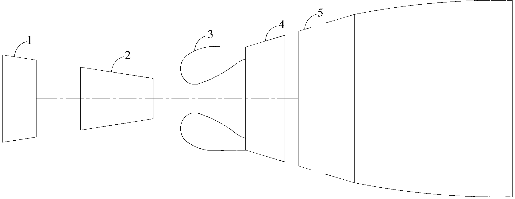
[0030] figure 1 It is a schematic diagram of the engine structure, including a low-pressure compressor 1, a high-pressure compressor 2, a combustion chamber 3, a high-pressure turbine 4 and a low-pressure turbine 5. When the engine is working, the air is compressed by the low-pressure compressor 1 and enters the high-pressure compressor 2. The high-pressure air then enters the combustion chamber 3 to burn with fuel. The high-temperature and high-pressure gas formed after combustion enters the high-pressure turbine 4 and low-pressure turbine 5, and passes through the turbine. Work is done to drive the high-pressure compressor 2 and the low-pressure compressor 1 respectively.

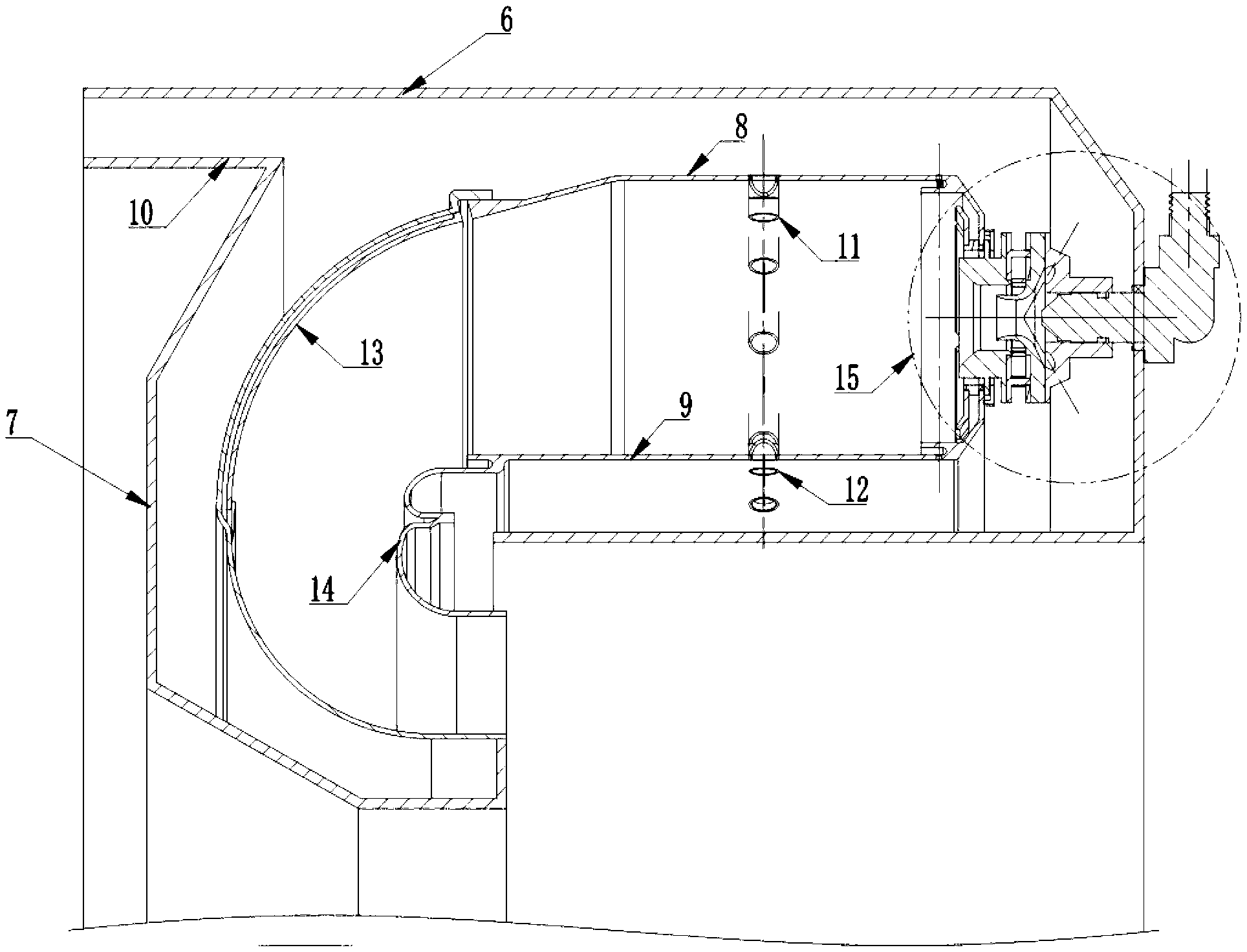
[0031] Such as figure 2 As shown, the combustion chamber 3 adopts a single-annular cavity structure, and the casing 6 outside the combustion chamber and the casing 7 in...


PUM


Abstract

The invention provides a beveling combustion hole rotation aiding low-pollution backflow combustion chamber which is of a single annular cavity structure. The beveling combustion hole rotation aiding low-pollution backflow combustion chamber is composed of combustion chamber boxes, a flame tube inner wall, a flame tube outer wall, a big bended tube, a small bended tube and combustion chamber heads, air entering from an inlet enters the combustion chamber through a diffuser, airflow is divided into three portions, the three portions of the airflow respectively enter the flame tube, the first portion of the airflow enters from the combustion chamber heads via swirl cups and head cooling holes, the second portion of the airflow enters the flame tube from main combustion holes, and the third portion of the airflow is used for cooling the flame tube wall and enters the flame tube from film holes and beveling holes formed in the inner wall of the flame tube, the outer wall of the flame tube, the wall of big bended tube and the wall of the small bended tube, and the airflow in the flame tube is discharged from the combustion chamber after combusting, being mixed and turning by 180 degrees. A swirl cup air atomizing nozzle is applied to each combustion chamber head, and a diffusive combustion organization mode is applied. Each inner ring main combustion hole of the flame tube and the flame tube wall surface form an angle with certain degrees in the circumferential direction, and each outer ring main combustion hole of the flame tube and the flame tube wall surface form an angle with certain degrees in the circumferential direction, and airflow of each inner ring main combustion hole and each outer ring main combustion hole and airflow of each upper wall main combustion hole, corresponding to one head swirl cup, of the flame tube and each lower wall main combustion hole, corresponding to one head swirl cup, of the flame tube form tangential airflow. The beveling combustion hole rotation aiding low-pollution backflow combustion chamber enables spray combustion to be more uniform, and can reduce pollutant discharge.

Description


Claims


Application Information

Patent Timeline
Owner BEIHANG UNIV
Why Eureka
Try Eureka