Oil burner with high viscosity

An oil burner, high-viscosity technology, applied in the direction of burner, combustion type, combustion method, etc., can solve the problems of unusable steam injection boiler, large burner flame size, etc., achieve good energy saving effect, complete combustion, and simple structure Effect

Active Publication Date: 2010-06-09
HARBIN GUANGHAN POWER TECH DEV CO LTD
View PDF0 Cites 1 Cited by
  • Summary
  • Abstract
  • Description
  • Claims
  • Application Information

AI Technical Summary

Problems solved by technology

[0004] The purpose of the present invention is to solve the problem that the fuel injector on the existing burner generally adopts mechanical atomization type, rotary cup type fuel injector and steam atomization type, and the flame size of the burner is large, so it cannot be used for steam injection boilers on offshore platforms The problem of providing a high viscosity oil burner

Method used


Image

  • Oil burner with high viscosity
  • Oil burner with high viscosity
  • Oil burner with high viscosity

Examples


specific Embodiment approach 1

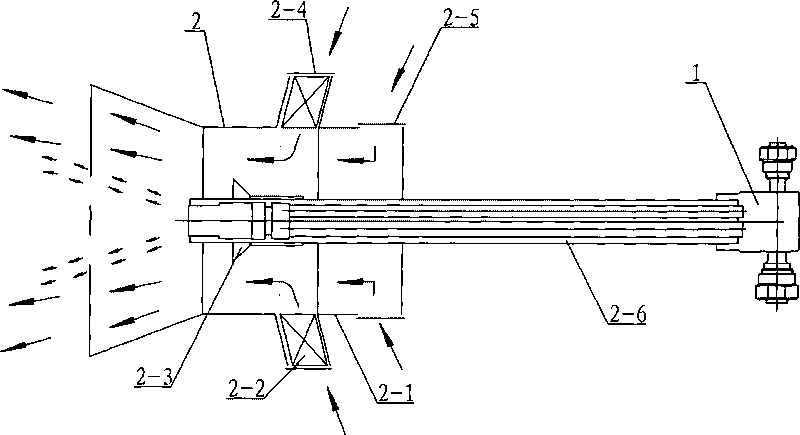
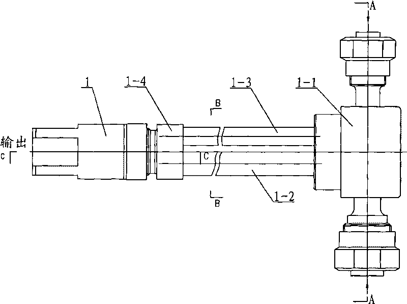
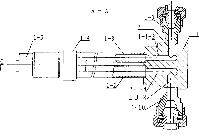
[0008] Specific implementation mode one: combine Figure 1 to Figure 10 Describe this embodiment, the burner of this embodiment is composed of fuel injector 1 and air regulator 2, and air regulator 2 is composed of air regulator body 2-1, swirler 2-2, stabilizing burner 2-3, cutting Composed of directional damper 2-4, axial damper 2-5 and central pipe 2-6, the output end of central pipe 2-6 is set in the inner cavity of air regulator body 2-1, and cyclone 2-2 is set in On the outer wall of the air regulator body 2-1, and the swirler 2-2 communicates with the inner cavity of the air regulator body 2-1, and the steady burner 2-3 is fixed on the output end of the central tube 2-6, The tangential damper 2-4 is set on the outer ring of the swirler 2-2, the axial damper 2-5 is set on the outer ring of the input end of the air regulator body 2-1, and the output end of the injector 1 is set on In the central tube 2-6, the fuel injector 1 is composed of a fuel injection seat 1-1, a fu...

specific Embodiment approach 2

[0009] Specific implementation mode two: combination Figure 7 To describe this embodiment, the inner diameter of the steam through hole 1-8-1 on the steam pan 1-8 in this embodiment is 3-5 mm larger than the outer diameter of the flange 1-7-7 on the atomizing sheet 1-7. It is designed to enter the burner 2-3 smoothly after the atomizing medium is mixed with the fuel oil. Other components and connections are the same as those in the first embodiment.

[0010] Working principle: Connect the atomizing medium pipe to the atomizing medium connecting pipe 1-10, connect the fuel pipe to the fuel connecting pipe 1-9, and the fuel passes through the fuel pipe through the second fuel hole 1-1-3, and the fuel pipe 1-2 The inner cavity of the fuel chamber 1-4-2, the first through hole 1-6-2, the second annular groove 1-6-1, the third annular groove 1-7-1, the first tangential groove 1-7 -3. The center hole 1-7-2 enters the steam through hole 1-8-1, and at the same time, the atomizing m...


PUM


Abstract

The invention provides an oil burner with high viscosity, relating to a burner, aiming at solving the problem that the fuel injector on the current burner generally adopts mechanical atomization type and spinning cup type and steam jet type, the flame size of the burner is great and can not be used in the offshore platform steam injection boiler. Fuel oil enters a steam through hole through a second fuel hole, a fuel chamber, a first through hole, a second circular groove, a third circular groove, a first tangential groove, a center hole via a fuel pipe, and simultaneously, the atomizing medium enters the inner cavity of the compression nut through a second atomizing medium hole and the steam cavity via the atomizing medium pipe, then enters the steam through hole via a second tangential groove and a fifth circular groove; the atomizing medium and the fuel mix in the steam through hole and enter the conical hole to obtain primary atomization under the action of the rotational centrifugal force; and the mixed oil is impacted violently by the wind from the tangential air door and the axial air door to obtain the secondary atomization. The invention is applied to the offshore platform steam injection boiler.

Description

technical field [0001] The invention relates to a burner. Background technique [0002] In recent years, a large amount of high-viscosity heavy oil has been found in several oilfields in my country's sea area for exploitation. Offshore oilfield development requires steam injection boilers, which inject high-pressure steam into underground oil layers to provide heat sources for thermal recovery. The fuel for steam injection boilers must use high-viscosity heavy oil from the oilfield. Steam injection boilers on offshore platforms are different from land-based equipment. The weight and size restrictions on steam injection boilers on offshore platforms are particularly strict. Therefore, it is required that the configured burner can achieve small flame size and stable and complete combustion to meet the requirements of the furnace of the boiler. [0003] The oil burner is mainly composed of two parts: the fuel injector and the air regulator. Existing fuel injectors generally a...

Claims


Application Information

Patent Timeline
Patent Type & Authority Applications(China)
IPC IPC(8): F23D11/00F23D11/44
Inventor 孙瑜珉陈明吴国松何兆彬张海龙张亮
Owner HARBIN GUANGHAN POWER TECH DEV CO LTD
Why Eureka
Try Eureka