
Testing device for testing soil phase transformation-constitutive coupling law, and method

A testing device and phase change technology, which can be used in soil testing, material inspection, etc., and can solve problems such as immaturity

Active Publication Date: 2013-09-11
CHONGQING JIAOTONG UNIVERSITY
View PDF6 Cites 8 Cited by
  • Summary
  • Abstract
  • Description
  • Claims
  • Application Information

AI Technical Summary

Problems solved by technology

[0003] Prior art methods have carried out a series of studies on the relationship between the critical state of soil phase transition, phase transition rate, etc., and the physical properties of soil and fluid during piping, and explored the relationship between soil phase transition law and soil particle size. Gradation, compactness, and the relationship between seepage velocity, seepage direction, etc., but the determination of how the stress state affects the phase transition of the soil, how the development of the phase transition affects the deformation of the soil, and other phase transition-constitutive coupling laws has not yet been formed. mature technical method

Method used


Image

  • Testing device for testing soil phase transformation-constitutive coupling law, and method
  • Testing device for testing soil phase transformation-constitutive coupling law, and method
  • Testing device for testing soil phase transformation-constitutive coupling law, and method

Examples


Embodiment 1

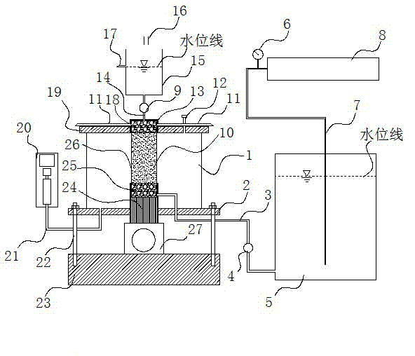
[0033] This embodiment discloses a soil phase transition-constitutive coupling law test device, which includes a confining pressure chamber 1, an axial stress application system 27, an upstream water head application system and a downstream water head application system.

[0034] The confining pressure chamber 1 includes a cylindrical body, and a top cover 19 and a bottom cover 2 respectively buckled with the upper and lower ends of the body. During the test, the test sample 10 is placed inside the confining pressure chamber 1 . In this embodiment, the basic structure of the confining pressure chamber 1 is the same as that of the common triaxial test, and it has good airtightness.

[0035] The axial stress application system 27 is located at the bottom of the confining pressure chamber 1 . The loading shaft 24 of the axial stress application system 27 penetrates the bottom cover 2 of the confining pressure chamber 1 and extends into the interior of the confining pressure cham...

Embodiment 2

[0042] This embodiment provides a method for testing using the soil phase transition-constitutive coupling law testing device described in Embodiment 1, characterized in that:

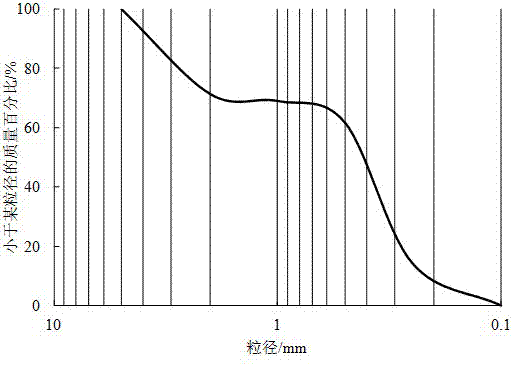
[0043] 1) Prepare the sample to be tested, put the sample to be tested into the confining chamber, and make its upper and lower ends respectively contact with the pebbles and gravels filled inside the cylindrical box body II and cylindrical box body I. In this embodiment, the pebble gravel The particle size is 2cm~5cm. As mentioned above in the description, the preparation method of the test sample can be prepared according to the method of ordinary triaxial test. In the embodiment, the sample is selected from the soil material with preset particle size distribution, and the sample is usually made according to the preset density and then saturated in vacuum for more than 2 hours. The diameter of the sample is selected according to the particle composition of the soil material. The sample diameter is r...


PUM


Abstract

The aim of the invention is to measure, under laboratory conditions, soil phase transformation-constitutive coupling law in piping processes, and namely to disclose a testing device for testing the soil phase transformation-constitutive coupling law, and a method. Through use of the method and the device, simulation and measurement of critical states and phase transformation rates of soil phase transformation in the piping processes under different stress conditions can be realized, and the measurement of influences of the soil phase transformation on soil stress-strain relationship also can be realized.

Description

technical field [0001] The invention belongs to the field of soil seepage deformation parameter testing, in particular to the testing of the interaction law between phase transition and constitutive relationship in the soil piping process. Background technique [0002] Piping is a phenomenon in which soil fine particles are carried out along the pores formed by skeleton particles under the action of seepage. Soil is a porous medium composed of solid particles of different sizes. When piping occurs, the solid particles in the soil change from the original static state to a moving state under certain hydraulic conditions. Therefore, the occurrence of piping is A process in which a part of a soil undergoes a phase transition. The phase transition law of soil during the piping process is mainly the critical condition and phase transition rate of phase transition. The development range of piping is small, the development speed is fast, and the process is complex. The critical ...

Claims


Application Information

Patent Timeline
IPC IPC(8): G01N33/24
Inventor 梁越刘楠楠王俊杰刘明维
Owner CHONGQING JIAOTONG UNIVERSITY
Learn More