Line inter-phase fault single-terminal location method implemented by aid of measured impedance amplitude characteristics of distributed parameters

A technology for distributing parameters and measuring impedance, applied in the field of power system relay protection, can solve problems such as high application cost, high sampling rate requirements, and inability to locate single-ended faults, achieving strong practical value and high ranging accuracy. Effect

Active Publication Date: 2013-09-11
STATE GRID CORP OF CHINA +3
View PDF4 Cites 10 Cited by
  • Summary
  • Abstract
  • Description
  • Claims
  • Application Information

AI Technical Summary

Problems solved by technology

The traveling wave method utilizes the transmission properties of fault transient traveling waves to perform single-ended fault location. It has high precision and is not affected by the operation mode and excessive resistance. However, it requires a high sampling rate, requires a special wave recording device, and has high application costs.
The impedance method uses the voltage and current after the fault to calculate the fault loop impedance, and performs single-ended fault distance measurement according to the characteristic that the line length is proportional to the impedance, which is simple and reliable, but the distance measurement accuracy is seriously affected by factors such as transition resistance and load current, especially When the transition resistance is large, the ranging result of the impedance method will seriously deviate from the real fault distance, and even the ranging failure will occur.
Due to the large distributed capacitive currents along the ultra-high voltage and ultra-high voltage transmission lines, when a medium-high resistance short-circuit fault occurs on the ultra-high voltage and ultra-high voltage transmission lines, the distance measurement results of the single-ended impedance method will seriously deviate from the real fault distance, which cannot meet the requirements of the site. application requirements
Therefore, the single-ended impedance method using lumped parameter modeling cannot be directly applied to the single-ended fault location of EHV and UHV transmission lines

Method used


Image

  • Line inter-phase fault single-terminal location method implemented by aid of measured impedance amplitude characteristics of distributed parameters
  • Line inter-phase fault single-terminal location method implemented by aid of measured impedance amplitude characteristics of distributed parameters
  • Line inter-phase fault single-terminal location method implemented by aid of measured impedance amplitude characteristics of distributed parameters

Examples


Embodiment Construction

[0015] The technical solution of the present invention will be further described in detail according to the accompanying drawings.

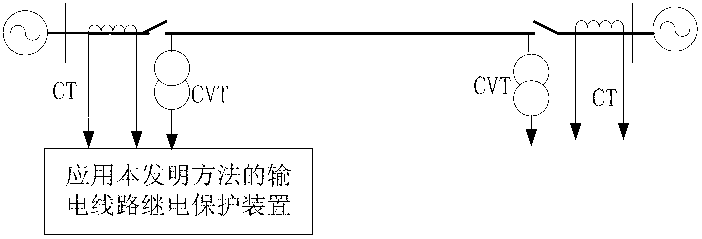
[0016] figure 1 It is a schematic diagram of the line transmission system applying the present invention. figure 1 CVT is a voltage transformer, and CT is a current transformer. The protection device samples the voltage of the voltage transformer CVT and the current waveform of the current transformer CT at the installation place of the transmission line protection to obtain the instantaneous value of the voltage and current, and then the protection device uses the Fourier algorithm to calculate the collected instantaneous value of the voltage and current Fault phase-to-phase voltage at transmission line protection installation , fault current between phases and negative sequence current between fault phases , as the input quantity; among them, φφ=AB, BC, CA phase.

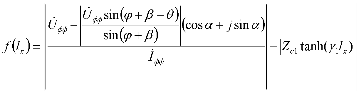
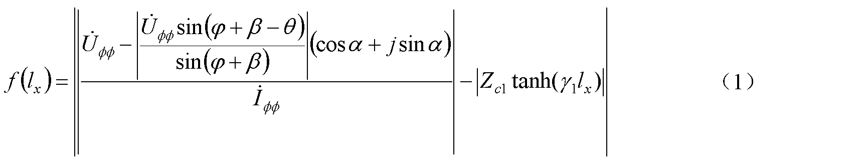
[0017] Protection device calculation Z c1 tanh (γ 1 l x )Angle ;

...


PUM


Abstract

The invention discloses a line inter-phase fault single-terminal location method implemented by the aid of measured impedance amplitude characteristics of distributed parameters. The line inter-phase fault single-terminal location method includes measuring fault inter-phase voltages, fault inter-phase currents and fault inter-phase negative-sequence currents at a power transmission line protection mounting position and using the fault inter-phase voltages, the fault inter-phase currents and the fault inter-phase negative-sequence currents as input variables; computing measured impedance of the distributed parameters, selecting an initial value I<x> of the fault distance, sequentially increasing a value of the fault distance by a step delta I on the basis of the initial value I<x>, sequentially computing an absolute value f(I<x>) of the difference between an impedance amplitude value of the distributed parameters of each point on a power transmission line and a measured impedance amplitude value of the distributed parameters until the increased value of the fault distance is equal to the total length of the power transmission line, and selecting the distance from the power distribution line protection mounting position to the point with the minimum value f(I<x>) as the fault distance. The line inter-phase fault single-terminal location method has the advantages that a physical model used in the method is a distributed parameter model, the location precision is unaffected by distributed capacitance currents, and the method is suitable for any voltage grades, and is particularly applicable to ultrahigh-voltage / extra-high-voltage power transmission line inter-phase short-circuit fault single-terminal location.

Description

technical field [0001] The invention relates to the technical field of electric power system relay protection, in particular to a single-end ranging method for phase-to-phase faults of lines by using distributed parameters to measure impedance amplitude characteristics. Background technique [0002] According to the division of electrical quantity sources, fault location methods are mainly divided into double-ended location methods and single-ended location methods. The double-terminal ranging method uses the electrical quantities at both ends of the transmission line to locate faults. It needs to obtain the electrical quantities at the opposite end through the data transmission channel, which is highly dependent on the data transmission channel. EHV and UHV transmission lines are often long-distance transmission lines, and the laying of data transmission channels required for distance measurement requires a large amount of additional investment. Therefore, the single-end di...

Claims


Application Information

Patent Timeline
Patent Type & Authority Applications(China)
IPC IPC(8): G01R31/08
Inventor 曾惠敏林富洪
Owner STATE GRID CORP OF CHINA
Why Eureka
Try Eureka