Method for Determining Radial Stress of Shock Absorber Annular Superimposed Valve Plate under Non-uniform Pressure

A technology of non-uniform distribution of pressure and radial stress, applied in the field of hydraulic shock absorbers, can solve the problems of not being able to provide analytical calculation formulas and calculation methods, and not being able to meet the requirements of shock absorber split design and strength check

Inactive Publication Date: 2016-03-02
SHANDONG UNIV OF TECH
View PDF4 Cites 0 Cited by
  • Summary
  • Abstract
  • Description
  • Claims
  • Application Information

AI Technical Summary

Problems solved by technology

However, the pressure on the superimposed valve plate of the shock absorber is non-uniform. For the calculation of the radial stress of the annular superimposed valve plate of the shock absorber under the non-uniform pressure, no accurate calculation method has been given before at home and abroad. At present, most of them use finite element simulation software to carry out numerical simulation calculations for superimposed valve plates under a given pressure by establishing a solid model. Different numerical values ​​obtained by different grid divisions are different to obtain different numerical solutions, and accurate analysis cannot be provided. Calculation formula and calculation method, therefore, can not meet the requirements of the modern CAD of the shock absorber and the actual split design and strength check of the superimposed valve plate

Method used


Image

  • Method for Determining Radial Stress of Shock Absorber Annular Superimposed Valve Plate under Non-uniform Pressure
  • Method for Determining Radial Stress of Shock Absorber Annular Superimposed Valve Plate under Non-uniform Pressure
  • Method for Determining Radial Stress of Shock Absorber Annular Superimposed Valve Plate under Non-uniform Pressure

Examples


Embodiment 1

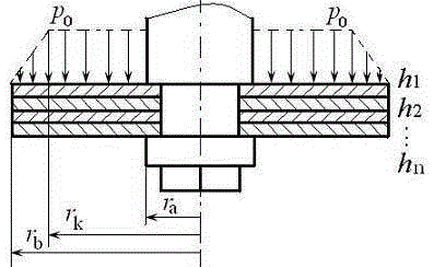
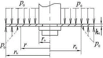
[0060] Example 1: The radius r of the inner circle of a circular superimposed valve plate of a certain shock absorber a =5.0mm, outer circle radius r b =8.5mm, valve port radius r k = 8.0mm, elastic modulus E = 200GPa, Poisson's ratio μ = 0.3, three different thicknesses of annular superimposed valve plates and the corresponding number of plates, respectively h 1 = 0.1 mm, n 1 = 3; h 2 = 0.15mm, n 2 = 2; h 3 = 0.2mm, n 3 = 1, in the interval [r a , r k ] distributed uniform pressure p 0 =3.0MPa, in the interval [r k , r b ] Distribution of pressure p = p 0 [1-(r-r k ) / (r b -r k )] MPa. Determine the radial stress of the annular superimposed valve plate of the shock absorber under non-uniform pressure.

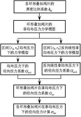
[0061] The method for determining the radial stress of the annular superimposed valve plate of the shock absorber provided by the example of the present invention under non-uniform pressure, its process is as follows image 3 As shown, the specific steps are as...

Embodiment 2

[0097] Embodiment 2: The inner circle radius, outer circle radius and material characteristics of the valve plate of a shock absorber valve plate superimposed are exactly the same as those in Example 1. The three different thicknesses of the superimposed valve plate and the corresponding number of plates are respectively h 1 = 0.1 mm, n 1 = 1; h 2 = 0.15mm, n 2 = 1; h 3 = 0.2mm, n 3 =1, valve port radius r k =7.0mm, in the interval [r a , r k ]Distributed uniform pressure p=p 0 =3.0MPa, in the interval [r k , r b ] Distribution of pressure p = p 0 [1-(r-r k ) / (r b -r k )] MPa. Determine the radial stress of the annular superimposed valve plate of the shock absorber under non-uniform pressure.

[0098] The calculation steps of Embodiment 1 are adopted, namely:

[0099] (1) Determine the equivalent thickness h of the annular stacked valve plate e :

[0100] According to the three different thicknesses of annular superimposed valve slices and the corresponding nu...

Embodiment 3

[0130] Embodiment 3: The material characteristic parameters, inner circle radius and valve position radius of a shock absorber annular superimposed valve plate are the same as those in Embodiment 1, and the outer circle radius r b =8.75mm, the two different thicknesses of stacked valve plates and the corresponding number of plates are h 1 = 0.15mm, n 1 = 1; h 2 = 0.2mm, n 2 = 3, in the interval [r a , r k ] distributed uniform pressure p 0 =3.0MPa, in the interval [r k , r b ] Distribution of pressure p = p 0 [1-(r-r k ) / (r b -r k )] MPa. Determine the radial stress of the annular superimposed valve plate of the shock absorber under non-uniform pressure.

[0131] The calculation steps of Embodiment 1 are adopted, namely:

[0132] (1) Determine the equivalent thickness h of the annular stacked valve plate e :

[0133] According to the two different thicknesses of stacked valve plates and the corresponding number h 1 = 0.15mm, n 1 = 1; h 2 = 0.20mm, n 2 = 3, d...


PUM


Abstract

The invention relates to a method for calculating radial stress of annular superposed valve slices of a shock absorber under nonuniform pressure and belongs to the technical field of shock absorbers. The method is characterized by including firstly, according to thickness and number of the annular superposed valve slices, calculating a thickness proportion coefficient of each superposed valve slice; secondly, according to structure and material characteristic parameters and radius of a valve port position, acquiring a radial stress coefficient of a ring under the nonuniform pressure; thirdly, according to the thickness proportion coefficients, the radial stress coefficient and a maximum nonuniform pressure, calculating radial stress of the annular superposed valve slices of the shock absorber at any radius position. Calculation examples and ANSYS simulation verification results show that the calculation method is correct, so that an accurate method for calculating radial stress of the annular superposed valve slices of the shock absorber is provided for designing and strength verifying of the shock absorber and the superposed valve slices, valve slice parameter design values are more reliable, designing and testing expenses can be reduced, design level, performance and quality of the shock absorber can be improved, and the service life of the shock absorber can be prolonged.

Description

technical field [0001] The invention relates to hydraulic shock absorber technology, in particular to a method for determining radial stress of an annular stacked valve plate of a shock absorber under non-uniform pressure. Background technique [0002] Shock absorber throttle valve plates are mostly annular superimposed valve plates, which are the most critical precision components in automobile shock absorbers, and their thickness is generally only 0.15mm to 0.3mm. The stress of annular superimposed valve plates affects the thickness of shock absorber superposed valve plates. Split design and strength check. At the same time, the stress of the valve plate determines the life of the shock absorber. Among them, the radial stress will cause the inner circle of the valve plate to break. However, the pressure on the superimposed valve plate of the shock absorber is non-uniform. For the calculation of the radial stress of the annular superimposed valve plate of the shock absorber...

Claims


Application Information

Patent Timeline
Patent Type & Authority Patents(China)
IPC IPC(8): G06F17/50
Inventor 周长城宋群华珍
Owner SHANDONG UNIV OF TECH
Why Eureka
Try Eureka