Battery winding machine and winding needle mechanism thereof

A battery roll and needle roll technology, applied in secondary batteries, non-aqueous electrolyte batteries, circuits, etc., can solve problems such as difficulty, affect structural stability, and poor needle extraction, and achieve high stability, simple structure, and easy installation. Easy to debug effects

Active Publication Date: 2013-09-11
SHENZHEN GEESUN INTELLIGENT TECHNOLOGY CO LTD
View PDF5 Cites 5 Cited by
  • Summary
  • Abstract
  • Description
  • Claims
  • Application Information

AI Technical Summary

Problems solved by technology

[0004] like figure 1 As shown, in the existing scheme, in order to ensure the coaxiality of the station relative to the two winding needles, it is required that the installation shaft of the winding needle 1 and the winding needle 2 of the station and the sliding sleeve 5, the sliding sleeve 5 and the rotating sleeve 6 1. The matching precision between the rotating sleeve 6 and the bearing seat 8 is high, and it is very difficult to complete the coaxiality requirements of the two rolls of needles relative to the station through too many shape and position tolerances; in addition, if figure 2 As shown, the gap L3 is reserved at the length section L1 of the winding needle 2, in order to avoid the diaphragm when the winding needle clamps the diaphragm, but when the winding needle 2 inserts (pulls out the needle), the length section L2 of the winding needle directly rubs against the diaphragm, This leads to some damage to the diaphragm or poor needle removal during the process of cell pin insertion (pin extraction), and the two roll pins cannot be used interchangeably; moreover, due to the complex structure and the positioning of the positioning pin 9, the installation and debugging of the roll pins are difficult. Difficulty, seriously affecting the stability of the structure

Method used


Image

  • Battery winding machine and winding needle mechanism thereof
  • Battery winding machine and winding needle mechanism thereof
  • Battery winding machine and winding needle mechanism thereof

Examples


Embodiment Construction

[0035] In order to make the object, technical solution and advantages of the present invention clearer, the present invention will be further described in detail below in conjunction with the accompanying drawings and embodiments. It should be understood that the specific embodiments described here are only used to explain the present invention, not to limit the present invention.

[0036] In addition, the technical features involved in the various embodiments of the present invention described below can be combined with each other as long as they do not constitute a conflict with each other.

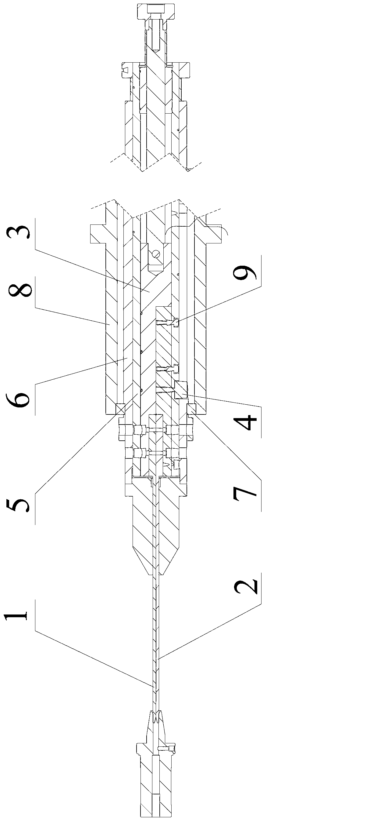
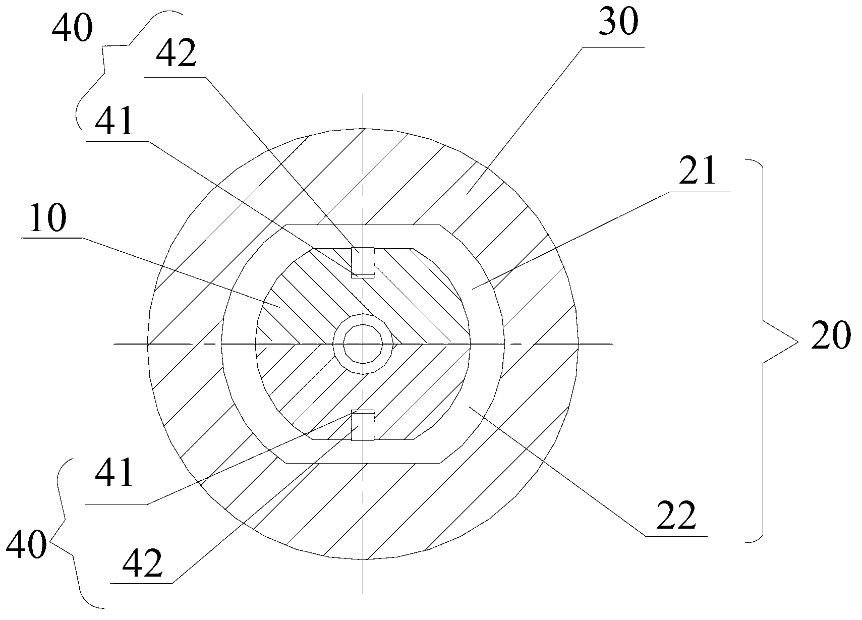
[0037] Such as image 3 , 4 As shown, the needle winding mechanism includes a needle winding assembly 10 , a needle pulling rod assembly 20 and a rotating sleeve 30 . In the battery winding machine, the winding needles of each station are assembled in pairs, so the winding needle assembly 10 in the present invention includes a first winding needle 11 and a second winding needle 12, an...


PUM


Abstract

The invention relates to the technical field of a battery winding machine, and provides a winding needle mechanism. The winding needle mechanism comprises a winding needle assembly, a needle withdraw rod assembly and a rotating sleeve, wherein the winding needle assembly comprises a first winding needle and a second winding needle; the needle withdraw rod assembly comprises a primary needle withdraw rod and a secondary needle withdraw rod, and the winding needle assembly is installed on the needle withdraw rod assembly through a positioning assembly; the needle withdraw rod assembly is sleeved and positioned inside the rotating sleeve, and the coaxial rotation of the rotating sleeve, the needle withdraw rod assembly and the winding needle assembly can be realized. The invention also provided with a battery winding machine. The winding needle mechanism and the battery winding machine can meet the concentricity requirement of relative stations of the winding needles.

Description

【Technical field】 [0001] The invention relates to the technical field of battery winding machines, in particular to a battery winding machine and a needle winding mechanism thereof. 【Background technique】 [0002] The needles of each station of the three-station circular full-automatic winding machine with single-sided needle removal are assembled in pairs, and the coaxiality requirements are very high, and it must be ensured that the needles of the two rolls will not damage the diaphragm when inserting (pulling) the needles. . This puts forward high requirements for the installation and debugging of the mechanism, the alignment of the winding cell, the needle rolling (pin pulling) and the stability of the equipment. [0003] In the prior art, the above problems are solved through the following schemes: as figure 1 , 2 As shown, two different rolling needles (rolling needle 1 and rolling needle 2) are respectively installed on a semicircular shaft 3, and a guide wheel 4 i...

Claims


Application Information

Patent Timeline
Patent Type & Authority Applications(China)
IPC IPC(8): H01M10/0587H01M6/14
CPCY02E60/10Y02P70/50
Inventor 曾文文阳如坤贺雁
Owner SHENZHEN GEESUN INTELLIGENT TECHNOLOGY CO LTD
Why Eureka
Try Eureka