
A multi-span rotor test bench with adjustable shaft sections and supports

A test bench and rotor technology, applied in the direction of aircraft component testing, etc., can solve the problems of shaft length, shaft diameter invariable, limited span adjustment range, time-consuming and laborious disassembly of bearings, etc., to achieve reliable testing, avoid additional vibration, and save costs. Effect

Active Publication Date: 2021-12-14
NANJING UNIV OF AERONAUTICS & ASTRONAUTICS
View PDF7 Cites 0 Cited by
  • Summary
  • Abstract
  • Description
  • Claims
  • Application Information

AI Technical Summary

Problems solved by technology

[0004] Existing multi-span rotor test benches generally have a limited adjustment range between spans, and the shaft length and shaft diameter cannot be changed. During the test process, adjusting the bearing position or replacing other accessories will cause inconsistent alignment and dismantling the bearing is time-consuming and laborious.
Chinese patent (CN 108007692A) proposes a split-type support structure test structure for a turboshaft engine double-rotor test bench, which effectively avoids dismantling other bearing seats or joints when changing the parameters of a certain bearing seat during the test process. However, if only the position of the bearing seat is changed, the bearing still needs to be disassembled. If you want to change the parameters of the shaft section, especially the shaft diameter, you need to change the structural parameters of the relevant parts of the test bench.

Method used


Image

  • A multi-span rotor test bench with adjustable shaft sections and supports
  • A multi-span rotor test bench with adjustable shaft sections and supports
  • A multi-span rotor test bench with adjustable shaft sections and supports

Examples


Embodiment Construction

[0041] The present invention will be further described below in conjunction with the accompanying drawings and embodiments.

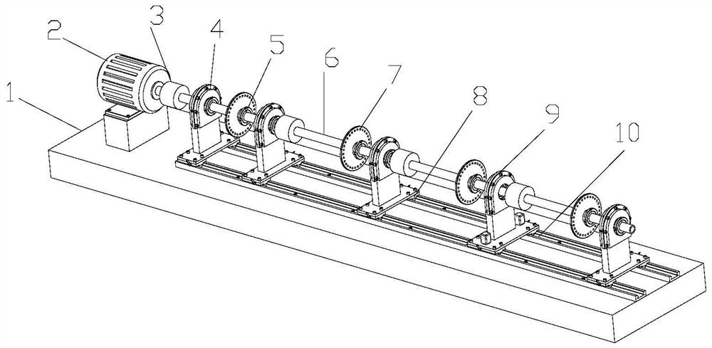
[0042] Such as figure 1 Shown is a multi-span rotor test bench with adjustable shaft sections and supports, including a base 1 and a drive motor 2 arranged on the base 1, a drive shaft module, a chute guiding and positioning module, a movable support module 4, and a self-defining Heart disk rotor module 7;

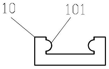
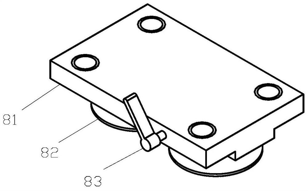
[0043]Wherein, the transmission shaft module includes a plurality of transmission shafts 6 and elastic diaphragm couplings 3, and the transmission between the drive motor 2 and the transmission shaft 6, and between the transmission shaft 6 and the transmission shaft 6 is realized through the coupling 3 in sequence; The chute guide positioning module includes a linear guide rail 10 arranged in parallel below the transmission shaft 6 and several slider assemblies 8 on the linear guide rail 10;

[0044] The movable support module 4 includes a support...


PUM


Abstract

The invention discloses a multi-span rotor test bench with adjustable shaft sections and supports, which comprises a driving motor arranged on a base, a transmission shaft module, a chute guiding and positioning module, a movable supporting module, and a self-centering disc rotor module The drive shaft module includes a number of drive shafts and couplings, the chute guide positioning module includes a slider assembly that slides along a linear guide rail; the movable support module includes a self-centering that is connected to the slider assembly through a support assembly The self-centering sleeve is locked and fixed to the transmission shaft through a locking assembly; the self-centering disk rotor module includes a counterweight disk that is locked and fixed to the transmission shaft through a locking assembly. The present invention has the characteristics of simple structure, convenient operation, reliable test, etc., can effectively guarantee high coaxiality between each shaft section, and can carry out experimental researches such as variable support position, variable shaft section length, variable shaft section outer diameter, etc. A practical and efficient rotor test system is provided, which greatly speeds up the research process.

Description

technical field [0001] The invention relates to a multi-span rotor test bench with adjustable shaft sections and supports, belonging to the technical field of rotor dynamics tests. Background technique [0002] Helicopter transmission system is a multi-stage, branched, gear meshing complex rotor system with non-parallel shafts. Among them, the tail transmission system is an important subsystem of the helicopter transmission system. Its function is to transmit power from the engine to the tail rotor through the transmission of torque and speed, balance the anti-torque torque generated by the rotor and realize the heading control of the helicopter. If there is a flaw in the design of the tail drive system, the tail drive shaft will cause strong vibration during high-speed rotation, which will break and damage the parts, resulting in the failure of the tail rotor control, which seriously threatens flight safety. During the flight of the helicopter, in addition to the heavy loa...

Claims


Application Information

Patent Timeline
Patent Type & Authority Patents(China)
IPC IPC(8): B64F5/60
Inventor 李苗苗李卓朱如鹏马亮亮肖俊孝陈健
Owner NANJING UNIV OF AERONAUTICS & ASTRONAUTICS
Learn More