Low voltage switch cabinet

A low-voltage switchgear and switchgear technology, applied in the cooling/ventilation of substation/switchgear, substation/distribution device shell, etc., can solve the problems of troublesome replacement, complicated component lines, etc. reasonable effect

Inactive Publication Date: 2013-09-11
NANTONG YAPU LIGHTING ELECTRICAL APPLIANCE MFG
View PDF5 Cites 4 Cited by
  • Summary
  • Abstract
  • Description
  • Claims
  • Application Information

AI Technical Summary

Problems solved by technology

The switchgear has the advantages of high breaking capacity, good dynamic and thermal stability, and safety and reliability. However, in the existing low-voltage switchgear, due to the large number of components, complicated lines, and relatively compact arrangement, it is relatively difficult to replace during maintenance. trouble

Method used


Image

  • Low voltage switch cabinet

Examples


Embodiment Construction

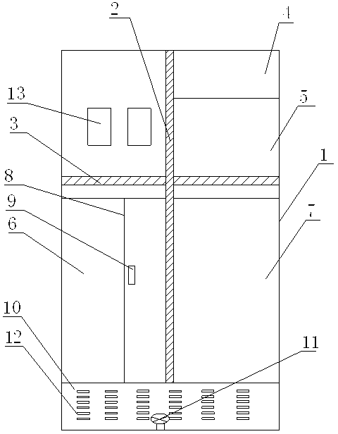
[0012] Such as figure 1 As shown, the low-voltage switch cabinet of the present invention includes a switch cabinet body 1, a middle partition 2 is provided in the middle of the switch cabinet body 1, a pull-out horizontal partition 3 is provided on the upper part of the switch cabinet body 1, and the switch above the horizontal partition 3 The cabinet body 1 is provided with a low-voltage chamber 4 and a circuit breaker chamber 5. The low-voltage chamber 4 is located above the circuit breaker chamber 5. The switch cabinet body 1 below the horizontal partition 3 is provided with a busbar chamber 6 and a cable chamber 7. The switch cabinet body 1 The lower part is provided with two closed doors 8 on which an automatic lock 9 is installed, and the bottom of the switch cabinet body 1 is provided with a cooling cabinet plate 10 .

[0013] A blower 11 is installed in the heat dissipation cabinet plate 10, and a heat dissipation seam 12 is provided on the heat dissipation cabinet pl...


PUM


Abstract

The invention discloses a low voltage switch cabinet which comprises a switch cabinet body. A middle partition plate is arranged in the middle of the switch cabinet body, a push-pull type horizontal partition plate is arranged on the upper portion of the switch cabinet body, a low voltage chamber and a circuit breaker chamber are arranged in the switch cabinet body above the horizontal partition plate, the low voltage chamber is located above the circuit breaker chamber, a bus chamber and a cable chamber are arranged in the switch cabinet body under the horizontal partition plate, two closed doors are arranged on the lower portion of the switch cabinet body, an automatic lock is installed on the doors, and a radiating cabinet plate is arranged at the bottom of the switch cabinet body. The low voltage switch cabinet has the advantage that the middle partition plate and the push-pull type horizontal partition plate are adopted to divide internal space of the switch cabinet into different sections, components and circuits are reasonable in arrangement, and enough radiating space is obtained.

Description

technical field [0001] The invention relates to a switch cabinet, in particular to a low-voltage switch cabinet. Background technique [0002] The switch cabinet is a kind of electrical equipment. The outside line first enters the main control switch in the cabinet, and then enters the sub-control switch. Each branch is set according to its needs. The switchgear has the advantages of high breaking capacity, good dynamic and thermal stability, and safety and reliability. However, in the existing low-voltage switchgear, due to the large number of components, complicated lines, and relatively compact arrangement, it is relatively difficult to replace during maintenance. trouble. Therefore, it is necessary to provide a new technical solution to solve the above problems. Contents of the invention [0003] The object of the present invention is to provide a low-voltage switchgear that is easy to maintain. [0004] The technical scheme adopted in the present invention is: [...

Claims


Application Information

Patent Timeline
Patent Type & Authority Applications(China)
IPC IPC(8): H02B1/30H02B1/56
Inventor 周洁
Owner NANTONG YAPU LIGHTING ELECTRICAL APPLIANCE MFG
Why Eureka
Try Eureka