Decoding circuit suitable for correcting miller code signal at high speed

A technology for decoding circuits and encoding signals, which is applied in the field of decoding circuits for high-speed correction of miller encoded signals, and can solve the problems of easy loss of decoding ability, limited pause period width, and complex circuits, etc.

Active Publication Date: 2013-09-11
上海航芯电子科技股份有限公司
View PDF3 Cites 14 Cited by
  • Summary
  • Abstract
  • Description
  • Claims
  • Application Information

AI Technical Summary

Problems solved by technology

The disadvantage of this method is that the circuit is complex, the width of the pause period solved is limited, and there are multiple narrow pause periods in

Method used


Image

  • Decoding circuit suitable for correcting miller code signal at high speed
  • Decoding circuit suitable for correcting miller code signal at high speed
  • Decoding circuit suitable for correcting miller code signal at high speed

Examples


Embodiment Construction

[0023] Specific embodiments of the present invention will be further described below in conjunction with the accompanying drawings.

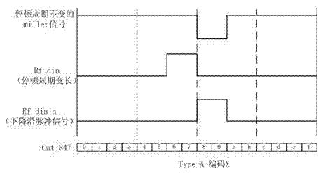
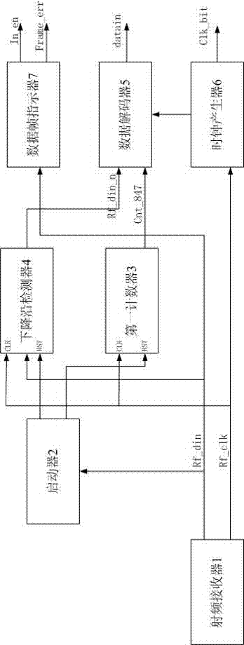
[0024] Such as figure 1 As shown, the present invention discloses a decoding circuit suitable for high-rate correction miller encoded signals, the decoding circuit includes: a radio frequency receiver 1, an initiator 2, a first counter 3, a falling edge detector 4, a data decoder 5 and Clock generator 6 and data frame indicator 7.

[0025] The radio frequency receiver 1 receives a radio frequency signal with a pause period, and outputs a baseband signal and a synchronous clock signal. The radio frequency receiver 1 conforms to the ISO / IEC14443A type protocol, and is used to receive a radio frequency (RF) signal with a pause period of, for example, 13.56MHz and a bit rate of 847kbps, and convert the received RF signal into a first clock suitable for a digital circuit Signal rf_clk and data signal rf_din. The radio frequency signal with a pause...


PUM


Abstract

The invention discloses a decoding circuit suitable for correcting a miller code signal at a high speed. The decoding circuit comprises a radio frequency receiver for receiving a radio frequency signal with a pause period and outputting a base-band signal and a synchronous clock signal; a starter for receiving the base-band signal and outputting a reset signal; a first counter for counting the synchronous clock signal; a falling edge detector for receiving the base-band signal, the synchronous clock signal and the reset signal and outputting a high-level pulse signal; a data decoder for decoding pause signals of both the first counter and the falling edge detector and outputting a decoded binary data signal; a clock generator for outputting a clock signal with a basic time unit period; and a data frame indicator for receiving the base-band signal and generating frame reception starting and ending signals and a frame error indication signal. The decoding circuit suitable for correcting the miller code signal at the high speed is simple, has strong anti-interference performance and generates the synchronous clock signal at the fixed frequency and ISO(International Standardization Organization)/IEC(International Electro-technical Commission)14443 protocol for data decoding.

Description

technical field [0001] The invention relates to a non-contact integrated circuit card and a decoding circuit in the field of near-distance wireless communication technology, in particular to a decoding circuit suitable for high-speed correction of miller coded signals. Background technique [0002] More and more non-contact products conforming to the ISO / IEC14443A type agreement have entered our lives, various types of bus cards, resident health cards, ID cards, department store cards, financial IC cards, near field communication (NFC) equipment, RFID electronic tags, etc. Recently, integrated circuit (IC) cards integrated with silicon chips have become popular due to their convenience, stability, security, and numerous applications. [0003] Compared with contact communication technology, contacts are easily oxidized and unstable. Non-contact short-distance communication has the advantages of high stability, high security, and high user experience, and is widely accepted a...

Claims


Application Information

Patent Timeline
IPC IPC(8): H03M13/00
Inventor 徐杰周玉洁
Owner 上海航芯电子科技股份有限公司
Why Eureka
Try Eureka