Supercharge Your Innovation With Domain-Expert AI Agents!

Nuclear fuel rod plenum spring assembly

A nuclear fuel element and nuclear fuel technology, applied in the field of fuel rod components, can solve problems such as inability to provide uniform pressure distribution

Active Publication Date: 2013-09-11
WESTINGHOUSE ELECTRIC CORP
View PDF5 Cites 0 Cited by
  • Summary
  • Abstract
  • Description
  • Claims
  • Application Information

AI Technical Summary

Problems solved by technology

It should be noted that due to the limited contact area corresponding to the end coil spring geometry, the plenum spring design does not provide a uniform pressure distribution on the top surface of the pellet as the pellet interface

Method used


Image

  • Nuclear fuel rod plenum spring assembly
  • Nuclear fuel rod plenum spring assembly
  • Nuclear fuel rod plenum spring assembly

Examples


Embodiment Construction

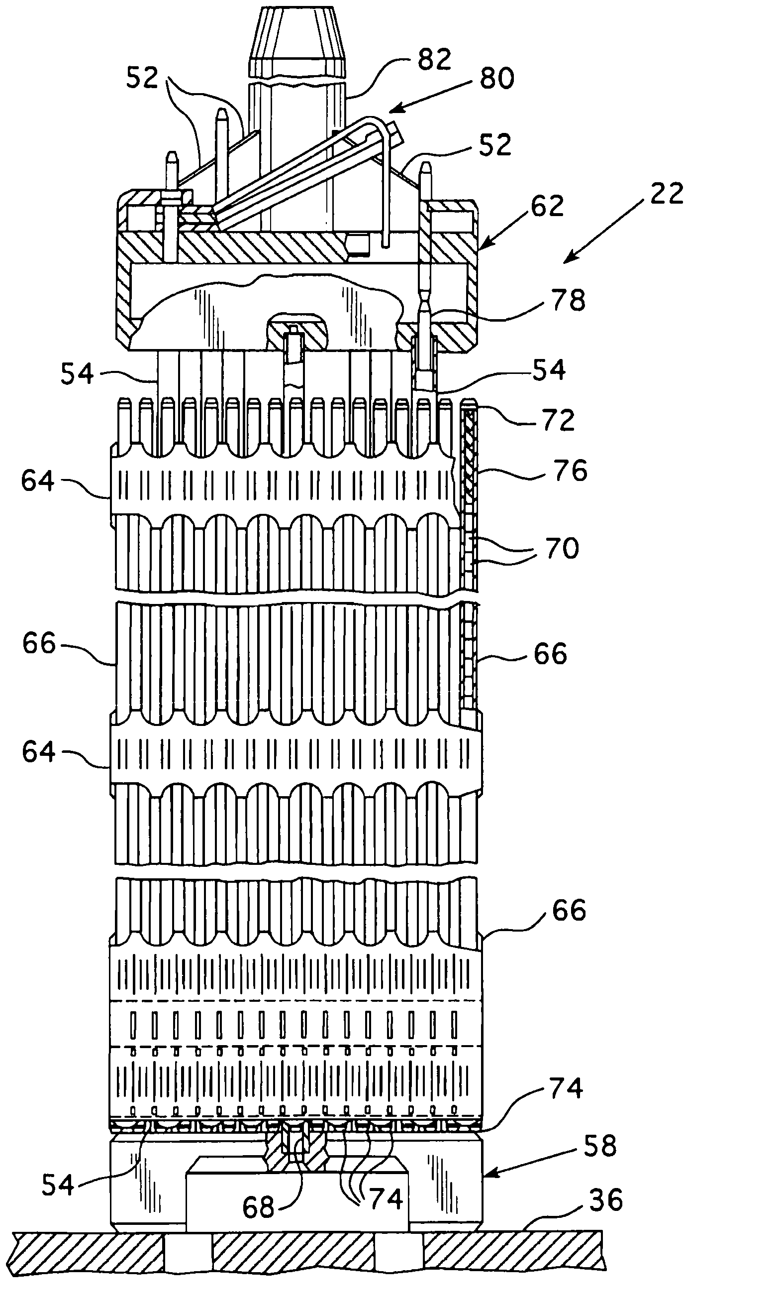
[0031] To achieve the foregoing objectives, the present invention introduces an intermediate section between the plenum spring and the top pellet of the fuel pellet stack, thereby creating an even contact distribution and reducing debris movement between the fuel rod plenum and the pellet stack possibility. A new intermediate element between the top core and the spring end coils is designed to provide even pressure distribution and reduce the possibility of debris migration. Ideally, the element is attached to an existing air chamber spring. In one embodiment, such as Figure 5 and 6 As shown, the intermediate element is a threaded spacer 86 that forms the interface between the plenum spring and the top surface of the top pellet. The spacer 86 is designed to provide uniform contact pressure on the top surface of the top pellet over its substantially flat head 88 and to reduce the possibility of movement of small pellet fragments. The threaded spacer also has features that ...


PUM


Abstract

A nuclear fuel rod plenum spring assembly has a spacer affixed to the lower end of the ground torsion spring. The spacer has a substantially flat surface on its underside that presses against the upper surface of the upper fuel pellets to spread the load of the spring over the top surface of the upper most fuel pellet.

Description

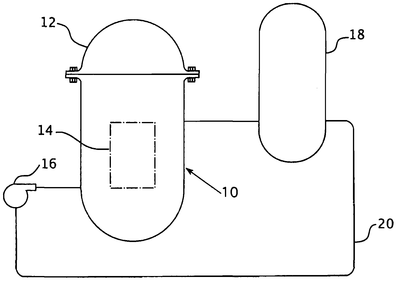
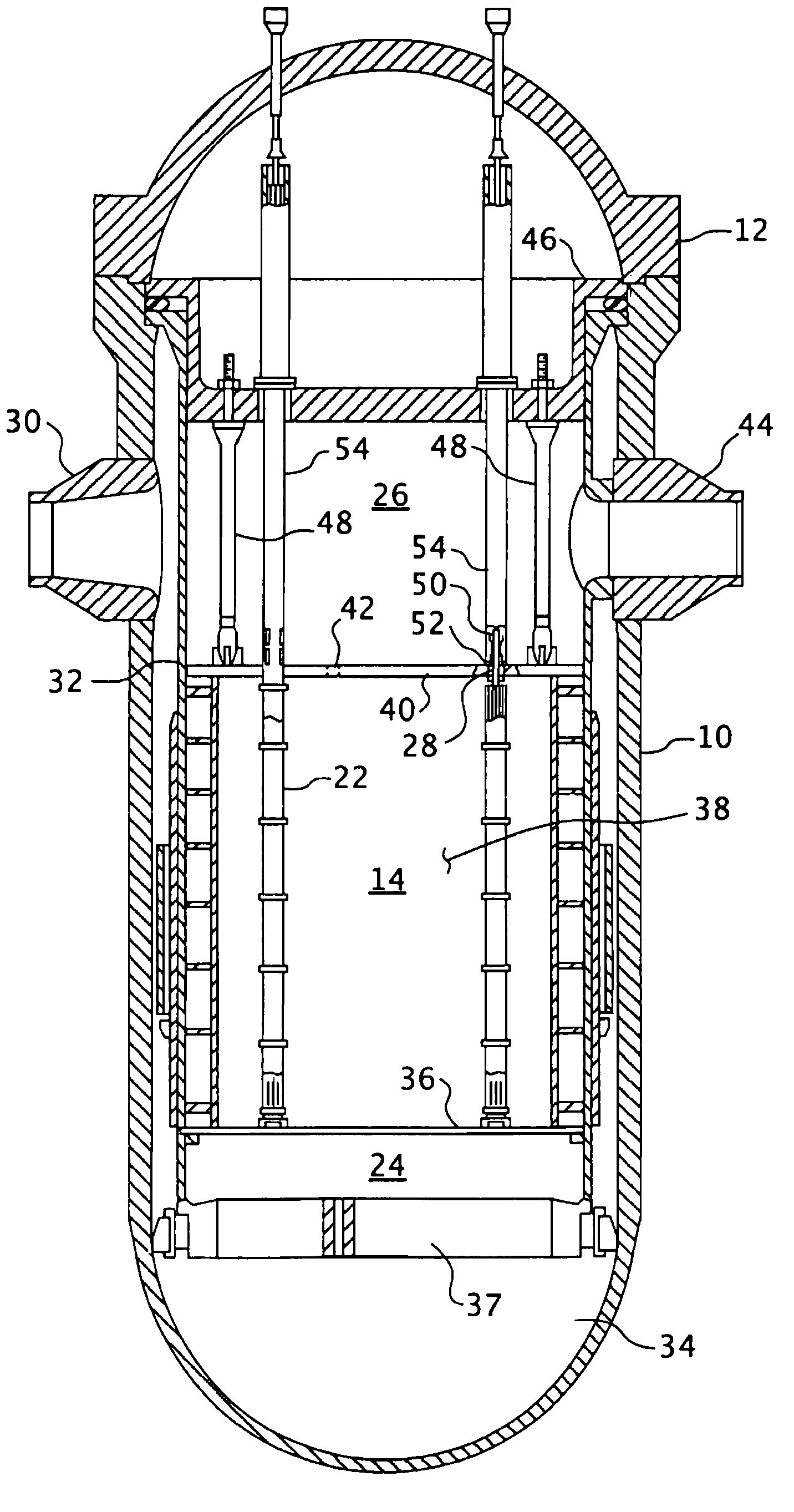
technical field [0001] The present invention relates generally to nuclear reactor internals, and more particularly to components such as fuel rods that use active components within the cladding held in place by plenum springs. Background technique [0002] The primary side of a pressurized water cooled nuclear reactor power generation system includes a closed loop that is isolated and in heat exchange relationship with a secondary side for the production of useful energy. The primary side consists of the reactor vessel surrounding the internal structure of the core, which supports a number of fuel assemblies containing fissile material, the primary circuit within the heat exchange steam generator, the interior space of the pressurizer, the tank for circulating pressurized water Pumps and tubes; the tubes connect each steam generator and pump independently to the reactor vessel. Each section of the primary contains steam generators, pumps and piping from the primary loop to ...

Claims


Application Information

Patent Timeline
Patent Type & Authority Applications(China)
IPC IPC(8): G21C3/18
CPCG21C3/16G21C3/18Y02E30/30
Inventor Y·阿勒欣S·H·格林A·阿特伍德H·沙阿
Owner WESTINGHOUSE ELECTRIC CORP
Features
  • R&D
  • Intellectual Property
  • Life Sciences
  • Materials
  • Tech Scout
  • Unparalleled Data Quality
  • Higher Quality Content
  • 60% Fewer Hallucinations
Learn More