
Switching power supply circuit

A switching power supply circuit, rectifier circuit technology, applied in the direction of high-efficiency power electronic conversion, electrical components, output power conversion devices, etc., can solve the problem of buzzing and other problems, and achieve the effect of suppressing buzzing and noise

Inactive Publication Date: 2013-09-11
PANASONIC CORP
View PDF5 Cites 4 Cited by
  • Summary
  • Abstract
  • Description
  • Claims
  • Application Information

AI Technical Summary

Problems solved by technology

That is to say, the existing switching power supply circuit has the problem of buzzing when it is in normal operation mode

Method used


Image

  • Switching power supply circuit
  • Switching power supply circuit
  • Switching power supply circuit

Examples


Embodiment Construction

[0017] Hereinafter, an embodiment of the present invention will be described with reference to the drawings.

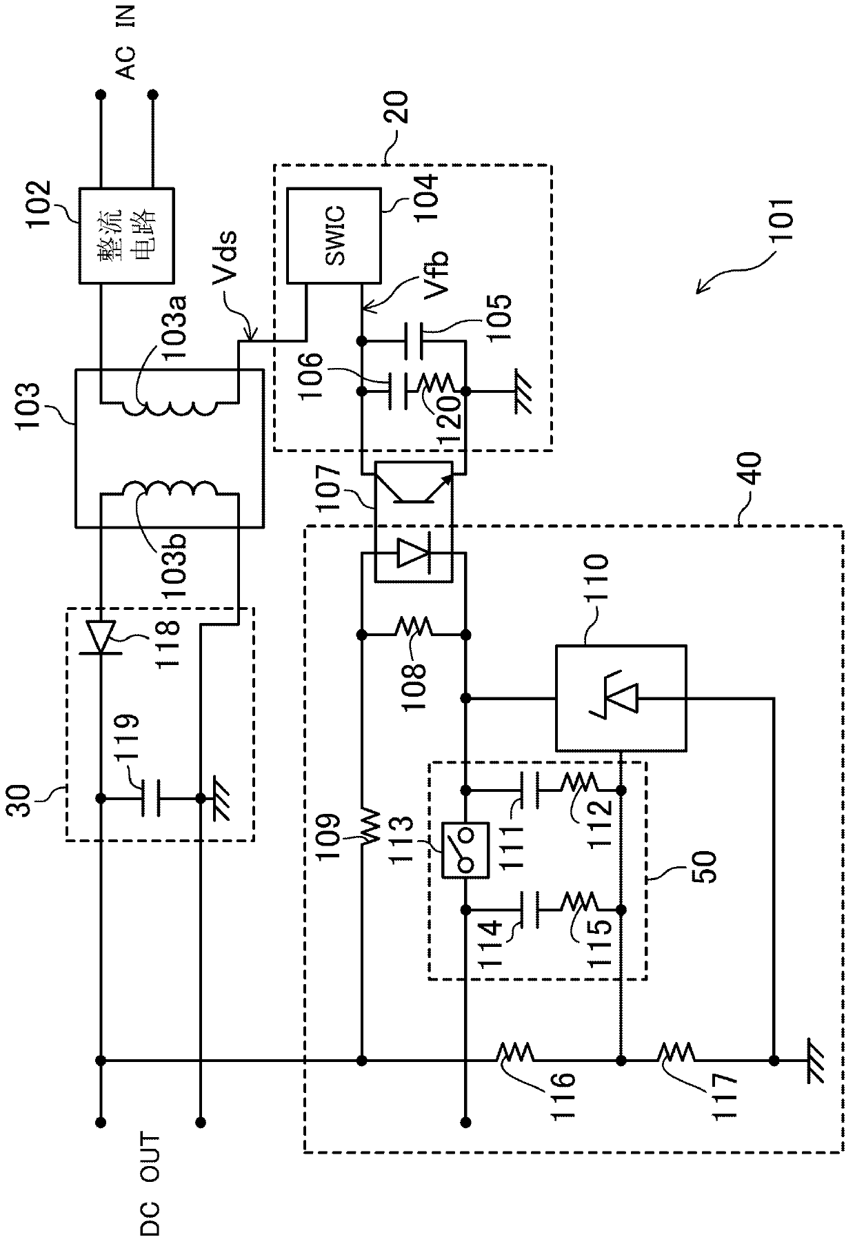
[0018] figure 1 It is a configuration diagram of a switching power supply circuit according to an embodiment of the present invention. The switching power supply circuit 101 includes a first rectification circuit 102 , a switching transformer 103 , a switching operation unit 20 , a second rectification circuit 30 and a control circuit 40 , and the switching power supply circuit 101 generates a direct current output power DC from an alternating current input power AC. In addition, the switching power supply circuit 101 is configured so that the operation mode of the switching power supply circuit 101 can be switched between the standby mode and the normal operation mode.

[0019] The first rectification circuit 102 rectifies, for example, commercial power input, that is, input power AC, converts it into direct current, and outputs it.

[0020] The switching transform...


PUM


Abstract

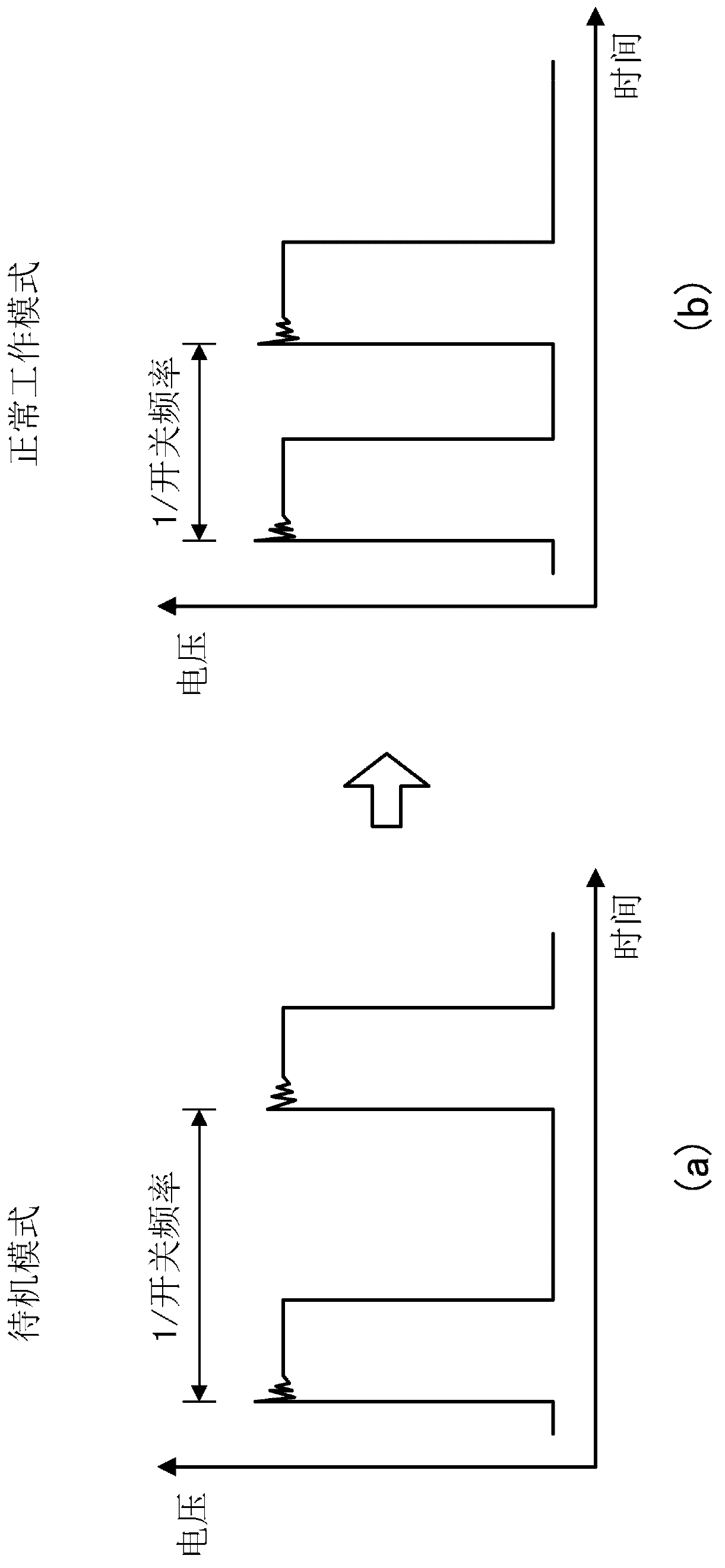
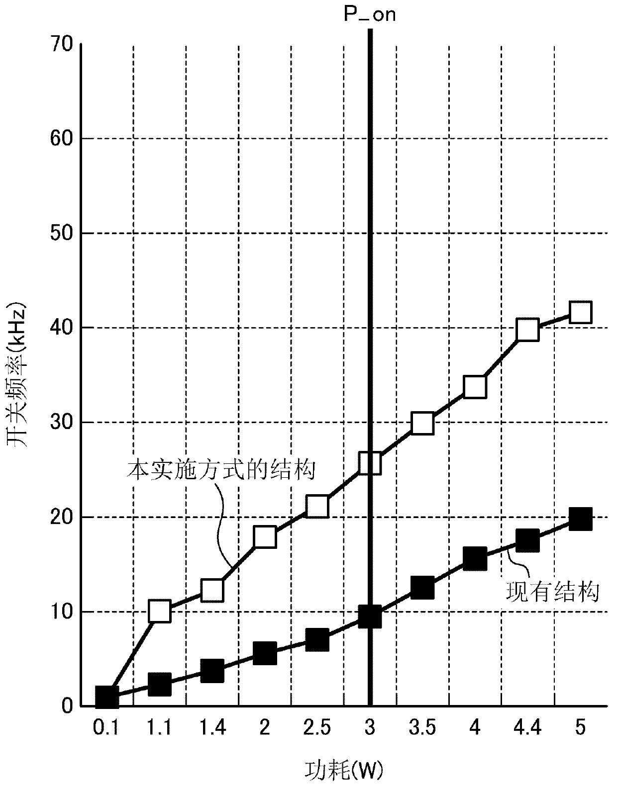
A switching power supply circuit (101) is provided with a first rectifier circuit (102) for converting AC to DC; a switching operation unit (20); a switching transformer (103) having a primary winding to which a switched current is supplied and a secondary winding for inducing power in response to the current; a second rectifier circuit (30) for rectifying the power induced in the secondary winding; and a control circuit (40) for changing, in each mode, the ratio of current flowing through a photo coupler (107) to the output voltage from the second rectifier circuit (30) so as to suppress the noise from the switching transformer while in standby mode and in power-on mode.

Description

technical field [0001] The present invention relates to a switching power supply circuit for audio system etc., especially relates to a switching power supply circuit with a standby mode. Background technique [0002] In recent years, the reduction in power consumption of electronic devices has been continuously pursued. In a switching power supply circuit used as a power supply of an electronic device, low power consumption can be achieved by controlling the switching operation of a switching element. As a conventional switching power supply circuit, there is disclosed a structure in which power consumption is reduced by reducing the switching frequency of the switching element in the standby mode while suppressing harsh abnormal noise (buzzing) from the transformer (for example, refer to Patent Document 1). [0003] Patent Document 1: Japanese Registered Utility Model No. 3095238 Contents of the invention [0004] -Technical problems to be solved by the invention- ...

Claims


Application Information

Patent Timeline
IPC IPC(8): H02M3/28
CPCH02M3/33523H02M3/33553Y02B70/10H02M1/0032
Inventor 田泽岳史
Owner PANASONIC CORP
Learn More