Rate optimized power consumption in micro wave radio links

A radio link and rate technology, used in radio link systems to control power consumption in radio link systems, can solve problems such as PA power consumption scaling, reduce failure interval time, reduce output power, operate The effect of temperature reduction

Active Publication Date: 2013-09-11
TELEFON AB LM ERICSSON (PUBL)
View PDF3 Cites 2 Cited by
  • Summary
  • Abstract
  • Description
  • Claims
  • Application Information

AI Technical Summary

Problems solved by technology

But even if B=1.1 (i.e., cutting the output power of the power amplifier (PA) in half will reduce the power consumption by 10%), the PA power consumption will scale significantly with the speed

Method used


Image

  • Rate optimized power consumption in micro wave radio links
  • Rate optimized power consumption in micro wave radio links
  • Rate optimized power consumption in micro wave radio links

Examples


Embodiment Construction

[0039] Embodiments herein relate to point-to-point duplex radio link systems based on time division (TD), frequency division (FD) or code division (CD).

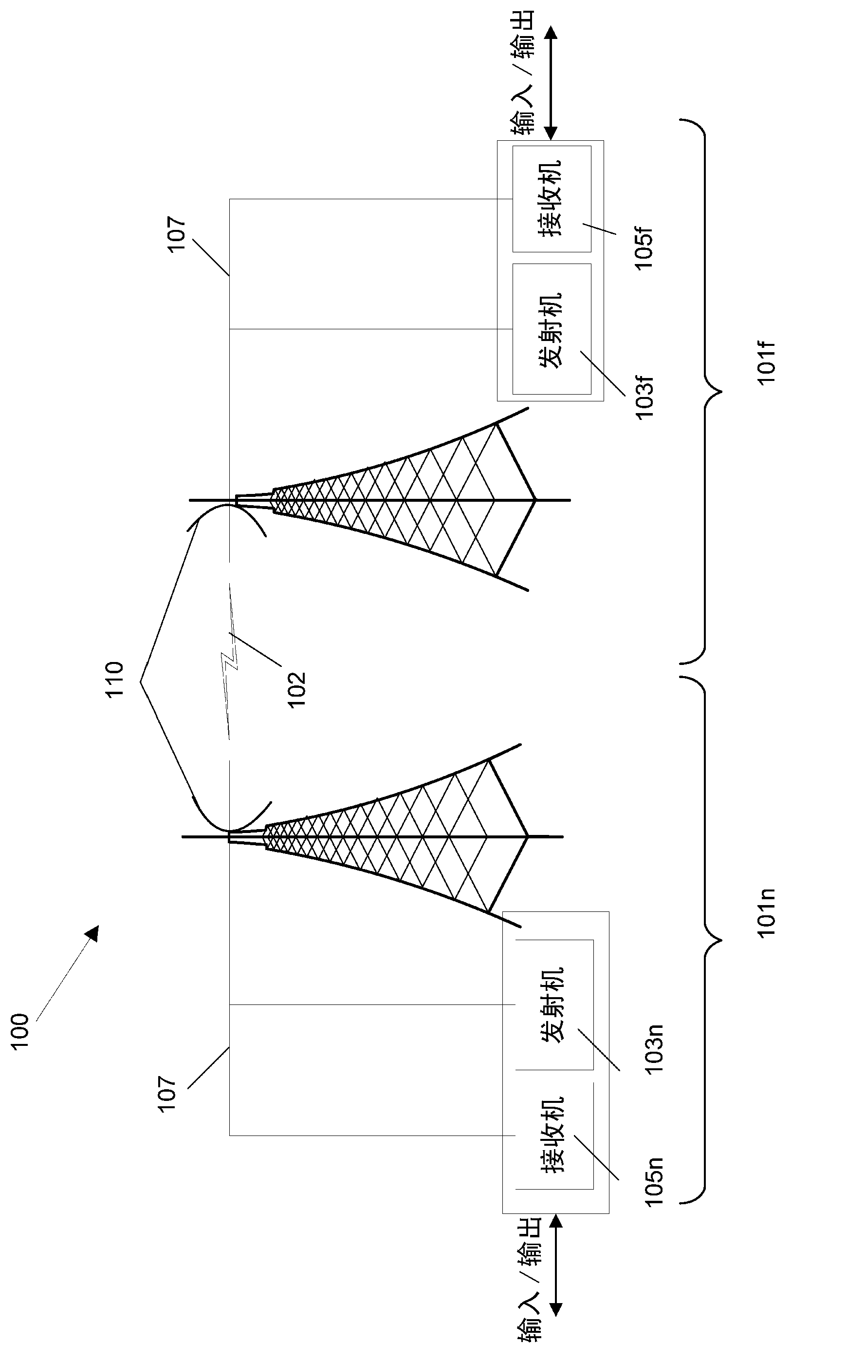
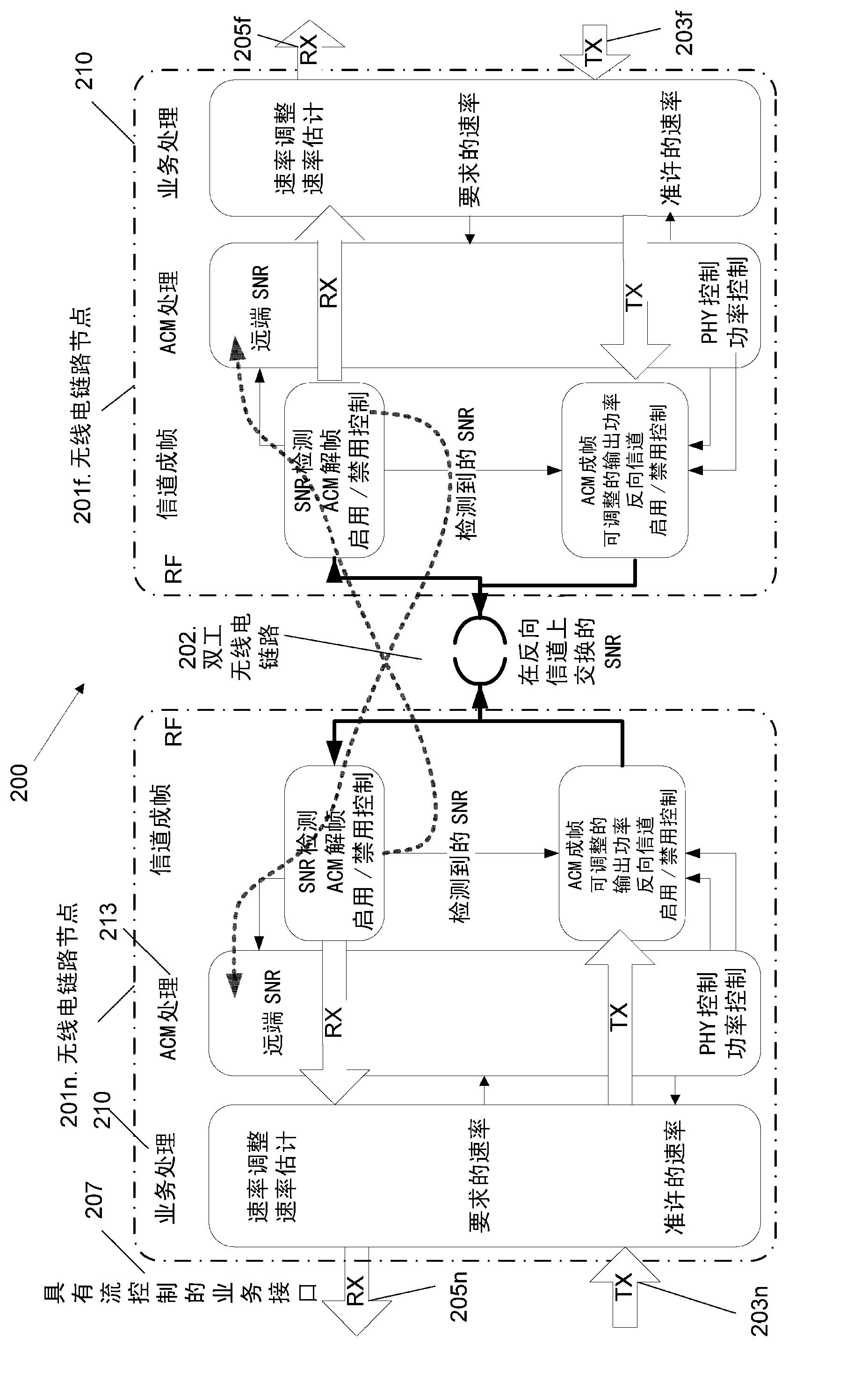
[0040] for example, figure 2 A single carrier duplex radio link system 200 is shown. Duplexing can be achieved by time division (TD), frequency division (FD), or code division (CD). The radio link system 200 comprises a near-end radio link node 201n and a far-end radio link node 201f connected via a data transmission system (eg a carrier duplex radio link / channel 202). The near-end radio link node 201n includes a near-end transmitter 203n and a near-end receiver 205n. The remote radio link node 201f includes a remote transmitter 203f and a remote receiver 205f. The information signal is provided eg to the traffic interface 207 of the near-end receiver 205n and is moved with the help of the radio link 202 to the far-end receiver 205f of the far-end radio link node 201f.

[0041] The radio link system 200 may be symmetric...


PUM


Abstract

The embodiments herein relate to a method in a near end radio link node (201n, 501n) for controlling power consumption in a radio link system (200, 500). The near end radio link node (201n, 501n) is connected to a far end radio link node (201f, 501f) via a radio link (202). The near end radio link node (201n, 501n) obtains a granted rate of traffic on the radio link (202) between the near end radio link node (201n, 501n) and the far end radio link node (201f, 501f). The near end radio link node (201n, 501n) obtains a demanded rate of the traffic between the near end radio link node (201n, 501n) and the far end radio link node (201f, 501f). The near end radio link node (201n, 501n) controls power consumption for the radio link system (200, 500) based on the granted rate and the demanded rate.

Description

technical field [0001] Embodiments herein generally relate to a near-end radio link node, a method in a near-end radio link node and a radio link system. More specifically, embodiments herein relate to controlling power consumption in radio link systems. Background technique [0002] A microwave radio link or radio link system is a communication system that uses a beam of radio waves to transmit signals or data between two locations. The locations can be at various distances from each other. exist figure 1 A simplified two-way radio link system 100 is shown in . The radio link system 100 comprises two radio link terminals / nodes 101 between which there is a data transmission system, eg a radio link / channel 102 . Radio link 102 may include one or more carriers. by will be in figure 1 The radio link node 101 shown at the left is used as a reference point, the radio link node 101 on the left may be referred to as a near-end radio link node 101n, and the radio link node 101...

Claims


Application Information

Patent Timeline
Patent Type & Authority Applications(China)
IPC IPC(8): H04W52/26H04W52/02H04L1/00
CPCH04L1/0003H04L1/0009H04L1/20H04W52/267H04W52/0206H04W52/02Y02D30/70H04W52/12
Inventor 佩-阿恩·托森罗伯特·林德格伦
Owner TELEFON AB LM ERICSSON (PUBL)
Why Eureka
Try Eureka