Riveting device

A riveting device and riveting technology are applied in the field of mechanical stamping processing, which can solve the problems of increasing the process of placing rivets, increasing the cost, and many processes, and achieving the effects of improving production efficiency, reducing labor intensity and reducing costs.

Active Publication Date: 2013-09-18
GREE ELECTRIC APPLIANCES INC
View PDF9 Cites 16 Cited by
  • Summary
  • Abstract
  • Description
  • Claims
  • Application Information

AI Technical Summary

Problems solved by technology

[0006] The first method not only needs to increase the process of placing rivets, which is inefficient, but also requires the use of rivets, which increases the cost; the second method requires two workpieces to go through multiple stamping processes to complete the holes and flanging on the workpiece Holes must be made before riveting. In this way, there are many processes, high cost and low efficiency.

Method used


Image

  • Riveting device
  • Riveting device
  • Riveting device

Examples


Embodiment Construction

[0030] It should be noted that, in the case of no conflict, the embodiments in the present application and the features in the embodiments can be combined with each other. The present invention will be described in detail below with reference to the accompanying drawings and examples.

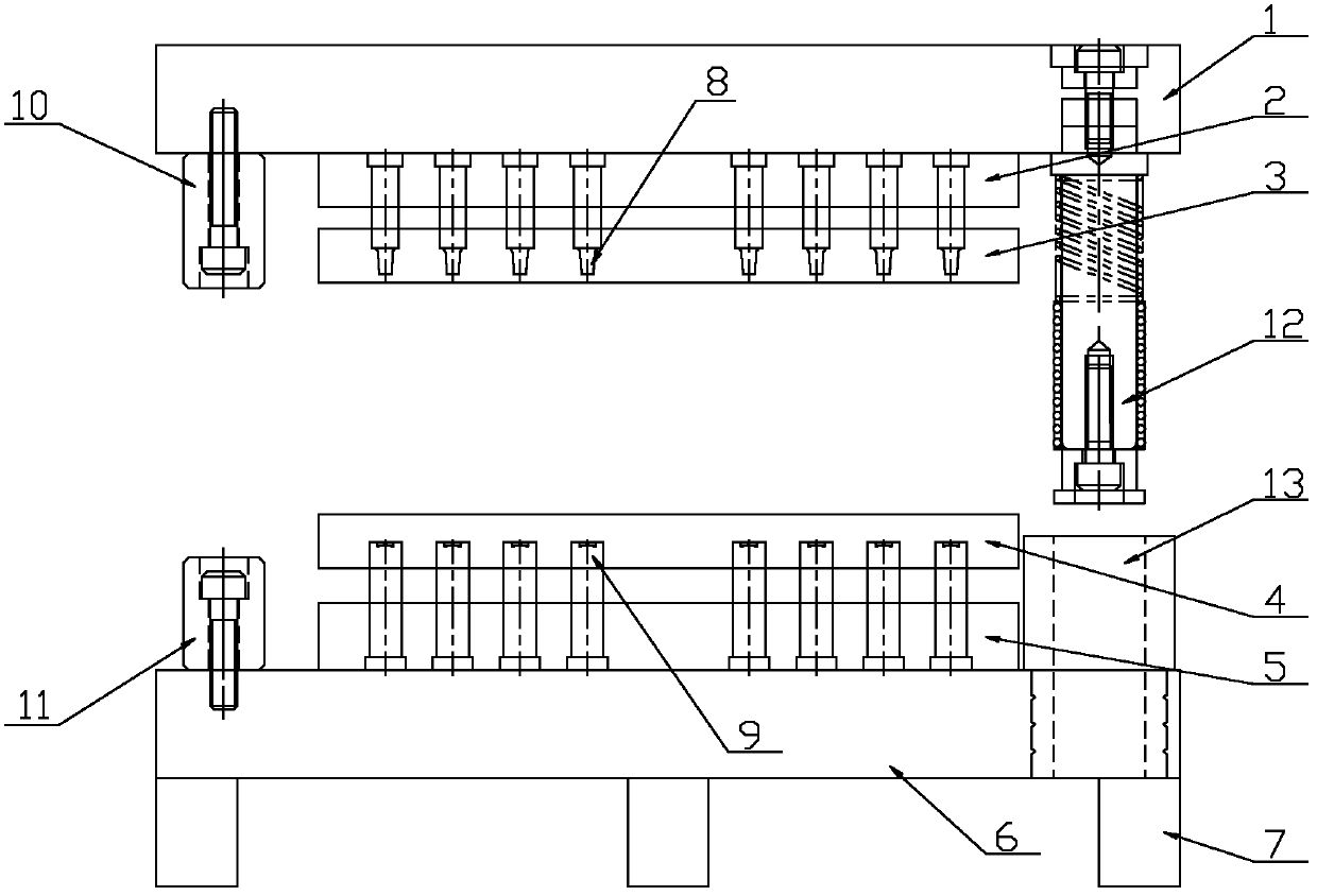
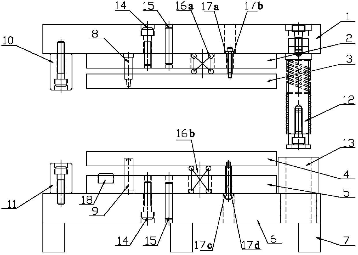
[0031] see in conjunction figure 1 with figure 2 , The riveting device of this embodiment includes: an upper mold mechanism and a lower mold mechanism. The upper mold mechanism is arranged movably along the longitudinal direction, and the upper mold mechanism includes a riveting punch 8; the lower mold mechanism is arranged below the upper mold mechanism, and the lower mold mechanism includes a riveting die 9 matched with the riveting punch.

[0032] In this embodiment, the working table (or other linear drive mechanism) on the punching machine is used to drive the upper mold mechanism to reciprocate up and down, and the separation and bonding of the riveting punch 8 and the riveting die 9 a...


PUM


Abstract

The invention provides a riveting device, which comprises an upper die mechanism and a lower die mechanism, wherein the upper die mechanism is movably arranged along the longitudinal direction and comprises a riveting punch head (8); and the lower die mechanism is arranged below the upper die mechanism and comprises a riveting female die (9) which is matched with the riveting punch head. According to the riveting device, the riveting is performed without using rivets, the material is saved, and a plurality of steps are not required to be performed, so that the cost is effectively reduced; and meanwhile, the riveting device has the advantages of easiness in operation, high riveting efficiency and capabilities of effectively improving the production efficiency and reducing the labor intensity of workers.

Description

technical field [0001] The invention relates to the technical field of mechanical stamping, in particular to a riveting device. Background technique [0002] There are mainly two types of riveting methods in the prior art: [0003] 1. Use rivets to rivet the workpiece. Lay the two punched workpieces together, then put the rivets into the punched holes of the two workpieces, and then use the mold to squeeze the rivets to deform to achieve the purpose of riveting. [0004] 2. Use the flanging hole to expand the hole and then perform riveting. Superimpose a punched workpiece ① and a turned workpiece ②, so that the hole of workpiece ① can be placed on the flanged hole of workpiece ②, and then use the mold to expand the flanged hole of workpiece ②. Riveting two workpieces together. [0005] There are certain defects in the above methods, as follows: [0006] The first method not only needs to increase the process of placing rivets, which is inefficient, but also requires the...

Claims


Application Information

Patent Timeline
Patent Type & Authority Applications(China)
IPC IPC(8): B21D39/00
Inventor 罗利宏陈明星熊志锋
Owner GREE ELECTRIC APPLIANCES INC
Why Eureka
Try Eureka