
Shield segment structure and shield tunnel

A technology of shield segments and shield tunnels, which is applied in tunnels, mining equipment, and earthwork drilling and mining, and can solve the problems of small effective use area of ​​circular sections, small size of rectangular sections, and poor mechanical performance of rectangular sections. Achieve the effect of reducing the excavation depth of the structure, improving the reliability of the connection, and improving the safety and reliability

Inactive Publication Date: 2013-09-18
SHANGHAI URBAN CONSTR DESIGN RES INST GRP CO LTD
View PDF4 Cites 21 Cited by
  • Summary
  • Abstract
  • Description
  • Claims
  • Application Information

AI Technical Summary

Problems solved by technology

Although the technology of shield tunnel with circular section is mature, it still has the following deficiencies: (1) the effective use area of ​​circular section is small, and the structural section cannot be fully utilized; (2) the amount of earthwork produced by shield tunneling during excavation is large , which directly increases the engineering cost of the tunnel; (3) The buried depth of the shield tunnel is about 1.0D (D is the diameter of the shield), which increases the excavation depth of the shield working well and the open-cut and buried section, which indirectly increases the Project risk and cost
[0004] (1) The mechanical performance of the rectangular section is poor, and the internal force of the section is large, resulting in an excessively large structural reinforcement ratio;
[0005] (2) The size of the existing rectangular section is small, which cannot meet the needs of urban economic development and municipal construction, especially cannot be used in underground municipal road projects;
[0006] (3) At present, the lining of large-section rectangular shield tunnels is still in the form of cast-in-place, which is not conducive to the construction period and quality control of the tunnel

Method used


Image

  • Shield segment structure and shield tunnel
  • Shield segment structure and shield tunnel
  • Shield segment structure and shield tunnel

Examples


Embodiment 1

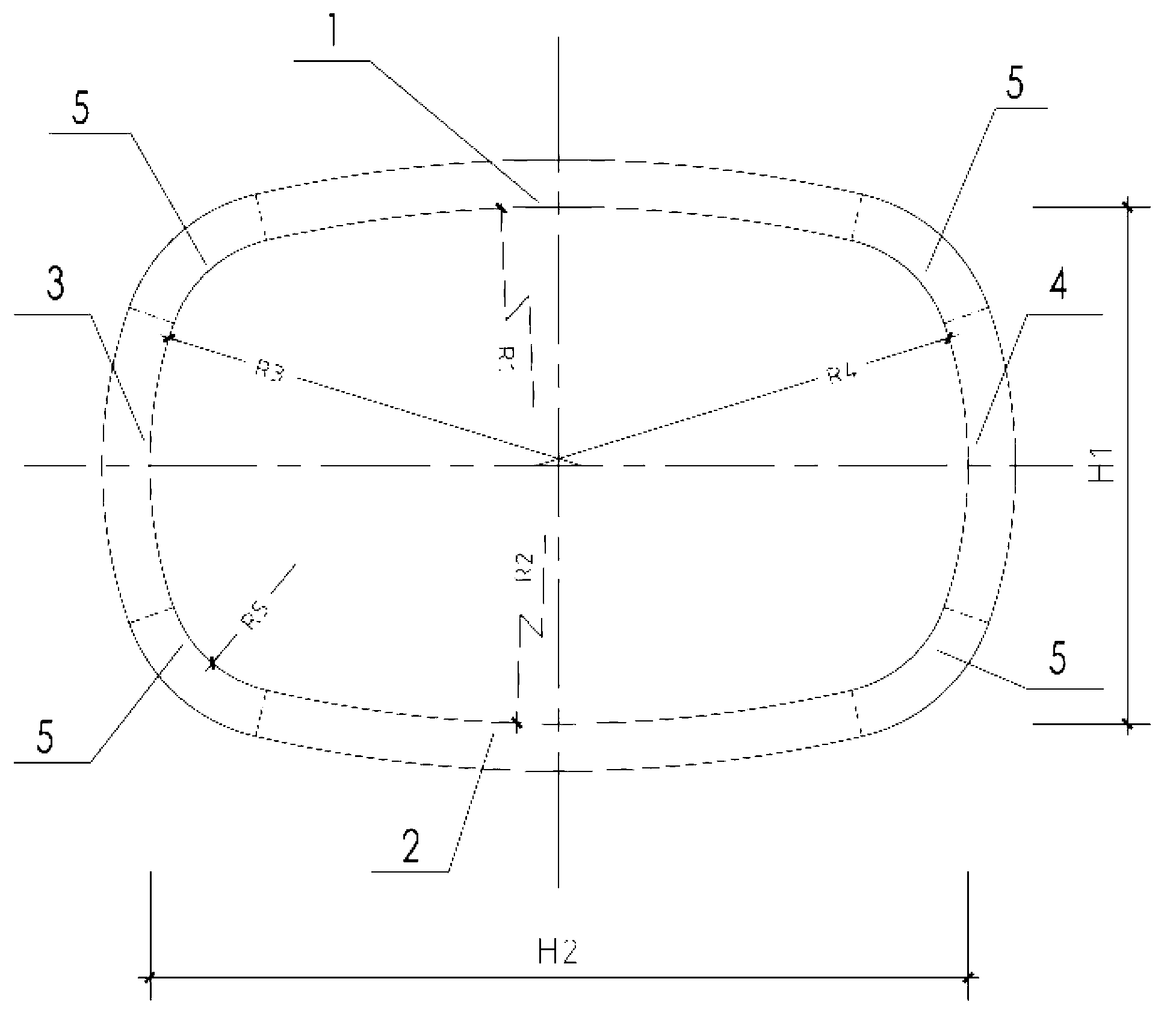
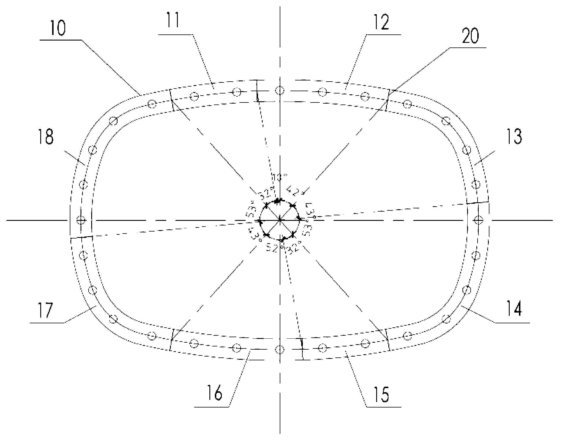
[0030] figure 1 It is a schematic diagram of the cross-sectional structure of the shield segment structure in Embodiment 1. like figure 1 As shown, a shield segment structure according to a specific embodiment of the present invention includes a plurality of segment segments 10, and the segment segments 10 are surrounded and spliced ​​to form a complete ring. Among them, such as figure 2 As shown, the cross-section of the entire ring is a center-symmetric and axisymmetric special-shaped surface, and the special-shaped surface is formed by enclosing eight sections of inferior arcs, which are respectively the top inverted arch 1 and the bottom inverted arch 2, which are arranged symmetrically up and down. The left arch 3 and the right arch 4 arranged opposite to each other symmetrically, and the four corners 5 . The two ends of the top inverted arch 1 are respectively connected to the two upper ends of the left arch 3 and the right arch 4 through a corner 5, and the two ends...

Embodiment 2

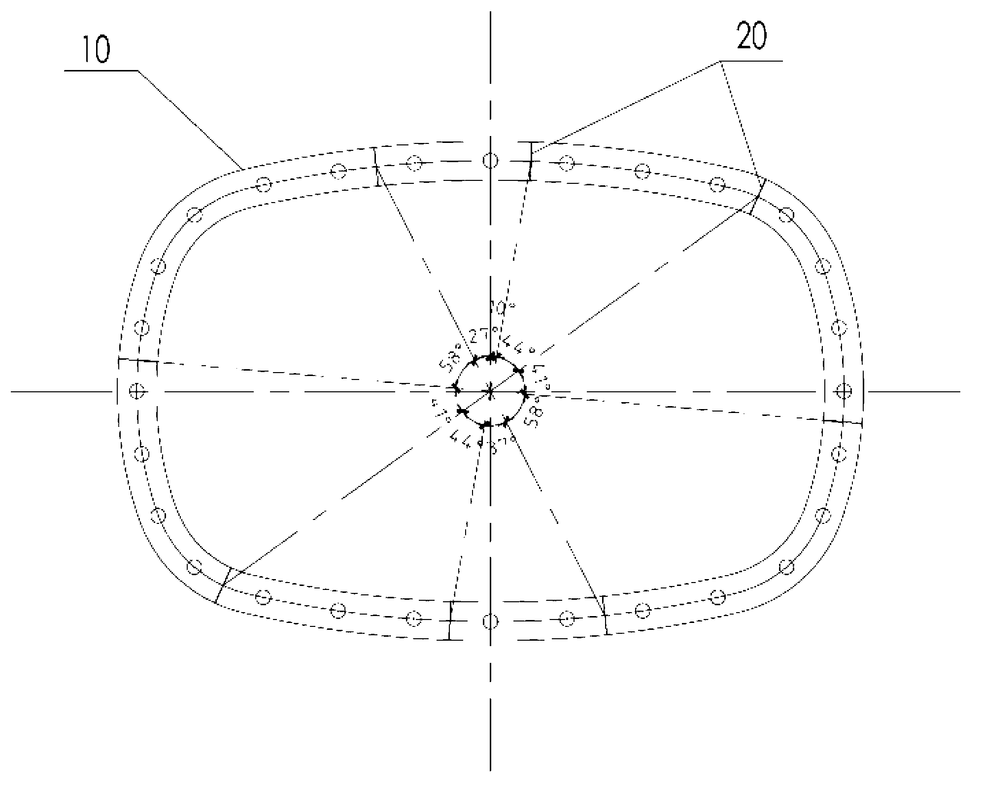
[0035] image 3 It is a schematic diagram of the cross-sectional structure of the shield segment structure of the second embodiment. like image 3 As shown, the shield segment structure of the second embodiment differs from the first embodiment in that the central angle of the segment 10 is different, and the position of the splicing seam 20 of adjacent segments is changed.

[0036] Of course, in other embodiments, the number of segments and their central angles can be selected according to the needs of the shield segment structure, which will not be repeated here.

Embodiment 3

[0038] Figure 4 It is a structural schematic diagram of the shield tunnel of the third embodiment. like Figure 4As shown, the shield tunnel of this embodiment includes the above-mentioned shield segment structure, and several shield segment structures are docked to form the shield tunnel, and the adjacent segments 10 of the shield segment structure 20 seams are set in a staggered manner. A positioning hole 30 for longitudinally extending connection is provided in the segment 10 , and several shield segment structures are sequentially connected in series by piercing the connecting piece in the positioning hole 30 .

[0039] Exemplarily, the shield tunnel of this embodiment adopts the shield segment structures of Embodiment 1 and Embodiment 2 to be assembled in series at longitudinal intervals to form a flat rectangular-like tunnel assembled in the form of staggered joints as a whole. According to the size of the segments 10, the screw holes are evenly distributed as the po...


PUM

PropertyMeasurementUnit
Thicknessaaaaaaaaaa

Abstract

The invention discloses a shield segment structure and a shield tunnel. The shield segment structure comprises a plurality of segments, wherein the segments are defined and spliced to form an integral ring; a cross section of the integral ring is a centrosymmetric and axisymmetric special-shaped face; the special-shaped face is formed by defining eight inferior arcs; the eight inferior arcs are a top inverted arch and a bottom inverted arch which are arranged vertically, oppositely and symmetrically, a left arch and a right arch which are arranged horizontally, oppositely and symmetrically, and four corners respectively; the segments are centrosymmetrically distributed on the integral ring; spliced seams, located on the cross section, of the adjacent segments are staggered with maximum internal force parts of the corners, and symmetry axes; a plurality of shield segment structures are butted to form the shield tunnel; and the spliced seams of the segments of the adjacent shield segment structures are arranged in a staggered manner. The shield segment structure and the shield tunnel can well integrate factors such as transverse internal force distribution of the shield tunnel, and connection of the longitudinal segments, so that the shield segment structure and the shield tunnel have good integrity, high efficiency and implementability.

Description

technical field [0001] The invention relates to the technical field of tunnel structures, in particular to a shield segment structure and a shield tunnel. Background technique [0002] In the soft soil area, the traditional shield tunnel is constructed by a single-round shield machine, and its cross-section is circular. With the continuous improvement of people's requirements for underground roads and rail transit, the scale of shield tunnels continues to increase, and almost all of them adopt the form of circular cross-sections. Although the technology of shield tunnel with circular section is mature, it still has the following deficiencies: (1) the effective use area of ​​circular section is small, and the structural section cannot be fully utilized; (2) the amount of earthwork produced by shield tunneling during excavation is large , which directly increases the engineering cost of the tunnel; (3) The buried depth of the shield tunnel is about 1.0D (D is the diameter of ...

Claims


Application Information

Patent Timeline
IPC IPC(8): E21D9/06
Inventor 姜弘潘国庆张银屏袁自鸣包鹤立
Owner SHANGHAI URBAN CONSTR DESIGN RES INST GRP CO LTD
Learn More