Double-layer water-cooled expansion joint

A technology of double-layer water cooling and expansion joints, applied in the field of expansion joints, can solve the problems of reducing the pressure bearing capacity of expansion joints, high maintenance costs, poor cooling effect, etc., and achieve the effects of faster flow speed, low manufacturing cost and improved service life

Active Publication Date: 2016-03-16
德阳市瑞祥机械厂
View PDF12 Cites 0 Cited by
  • Summary
  • Abstract
  • Description
  • Claims
  • Application Information

AI Technical Summary

Problems solved by technology

[0005] However, the existing technology represented by the above-mentioned patent documents still has the following defects in the actual use process: 1. The expansion joint is only provided with a water jacket on the outer surface of the connecting pipe, and there is a water jacket between the connecting pipe and the water jacket. There is a certain gap between the jacket and the connecting pipe for the radially positioned round steel. When the high-temperature medium passes through the expansion joint, the cooling effect of the cooling water on the connecting pipe is poor, and the connecting pipe is still easy to deform; 2. Since the water jacket is set between the flange and the Between the pressure-bearing ring plates, there is no cooling water passing through the flange, so the cooling effect of the water jacket on the flange is poor. When the high-temperature medium passes through the expansion joint, the joint between the flange and the pipe is easily deformed, and it is easy to affect the expansion joint and the joint. The tightness between the pipes; 3. The gap between the two connecting pipes not only hinders the smooth passage of high-temperature media, but also reduces the pressure bearing capacity of the expansion joint; 4. The structure of the expansion joint is complex, and there are high manufacturing costs and maintenance Disadvantage of high cost; 5. When the expansion joint compensates and adjusts the axially displaced pipeline, the set zirconium-containing fiber cotton is easy to loosen, resulting in poor high temperature resistance and corrosion resistance; 6. Set in the bellows The zirconium-containing fiber cotton between the lining cylinder and the main function of temperature and heat insulation, but it cannot take away the heat of the high-temperature medium, and has the disadvantage of poor cooling effect
In this patent, since there is no cooling device in the expansion joint, it is not suitable for use in pipelines that circulate high-temperature media. Even if the expansion joint is used in a pipeline that circulates high-temperature media, the expansion joint is easily deformed and damaged, and it is easy to occur during work. security incident

Method used


Image

  • Double-layer water-cooled expansion joint
  • Double-layer water-cooled expansion joint

Examples


Embodiment 1

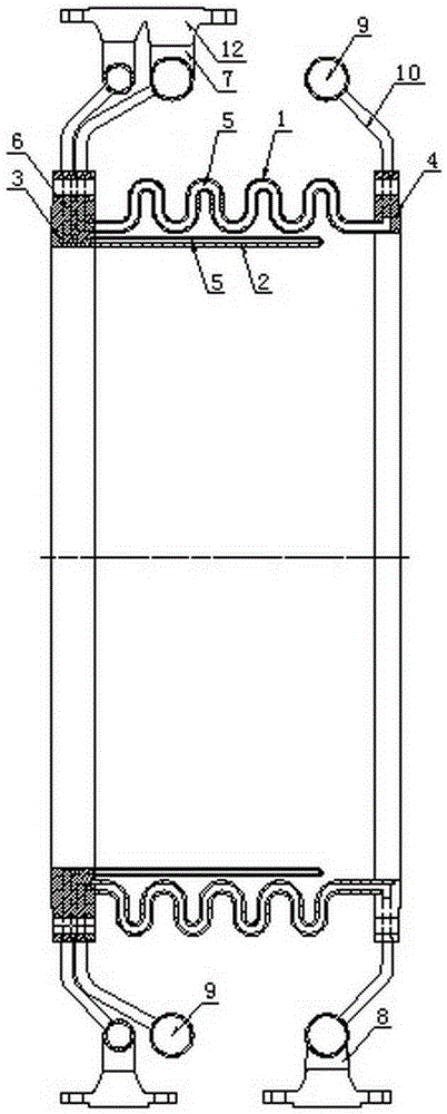
[0033] A double-layer water-cooled expansion joint, including a bellows 1, a guide tube 2, a first flange 3 and a second flange 4, and the two ends of the bellows 1 are respectively fixed to the first flange 3 and the second flange 4 connection, the guide tube 2 is fixedly sleeved in the bellows 1, and also includes a first water inlet and outlet device and a second water inlet and outlet device, and the walls of the bellows 1 and the guide tube 2 are provided with cavities 5 , the first flange 3 is provided with two inner cavities 6, the second flange 4 is provided with an inner cavity 6, and one of the inner cavities 6 of the first flange 3 passes through the cavity 5 of the bellows 1 and The inner cavity 6 of the second flange 4 communicates, and the other inner cavity 6 of the first flange 3 communicates with the cavity 5 of the guide tube 2. The first water inlet and outlet device, the first flange 3, the bellows 1 The first cooling system is formed after being connected ...

Embodiment 2

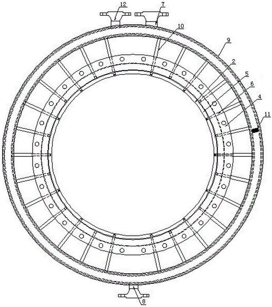
[0042] This embodiment is the same as the above embodiment, the main difference is that the second water inlet and outlet device includes a water diversion ring pipe 9, a water inlet 8, a water outlet 7 and a connecting pipe 10, and the water inlet 8 and the water outlet 7 are symmetrical It is arranged on the water diversion ring pipe 9 , and the water diversion ring pipe 9 is sleeved on the corrugated pipe 1 and communicates with the inner cavity 6 of the first flange 3 through the connecting pipe 10 . But the quantity of water diversion ring pipe 9 in the second water inlet and outlet device also can be set to two, during installation, the setting direction of water inlet 8 and water outlet 7 in the second water inlet and outlet device is preferably the same as that of the first water inlet and outlet device. The setting directions of the water port 8 and the water outlet 7 are the same.

Embodiment 3

[0044] This embodiment is the same as the above embodiment, the main difference is that: the number of connecting pipes 10 between each water diversion ring pipe 9 and the flange is 12.


PUM


Abstract

The invention discloses a double-water-cooling expansion joint, which comprises corrugated pipes, draft tubes, first flanges, second flanges, a first water inlet / outlet device and a second water inlet / outlet device, wherein the two ends of each corrugated pipe are fixedly connected with one first flange and one second flange respectively; the draft tubes are fixedly sleeved with the corrugated pipes; cavities are formed both in the pipe walls of the corrugated pipes and the tube walls of the draft tubes; two inner chambers are formed in each first flange; an inner chamber is formed in each second flange; one of the inner chambers in one of the first flanges is communicated with one of the inner chambers of one of the second flanges through the cavity of one of the corrugated pipes; the other inner chamber of one of the first flanges is communicated with the cavity of one of the draft tubes; the first water inlet / outlet device, one of the first flanges, one of the corrugated pipes and one of the second flanges are connected to form a first cooling system; the second water inlet / outlet device, the other first flange and the other draft tube are connected to form a second cooling system. The double-water-cooling expansion joint can lower the temperature of the expansion joint in the high temperature state, ensures that the expansion joint performs steady operation and is not deformed, can improve the safety of the expansion joint and can prolong the service life of the expansion joint.

Description

technical field [0001] The invention relates to an expansion joint, in particular to a double-layer water-cooled expansion joint, which is mainly suitable for compensation and adjustment of axial displacement of pipelines under high temperature conditions. Background technique [0002] At present, conventional expansion joints are mainly used to compensate and adjust the axial displacement of the pipeline when the pipeline expands with heat and contracts with cold. It is a kind of compensation element and is therefore widely used in various industries. However, when some high-temperature media with a temperature exceeding 800°C pass through the expansion joint, since the conventional expansion joint has no cooling system, the temperature of the expansion joint is relatively high, and it is easy to deform during operation, thereby affecting the stability and operation of the entire pipeline structure. safety. [0003] In order to solve the above problems, the following techn...

Claims


Application Information

Patent Timeline
Patent Type & Authority Patents(China)
IPC IPC(8): F16L51/02
Inventor 刘孙祥代友利
Owner 德阳市瑞祥机械厂
Why Eureka
Try Eureka