Device for disposing harmful gases

A harmful gas and deflection device technology, which is applied in the direction of burner, combustion method, combustion type, etc., can solve the problems of restarting, continuous operation of the flame root repeatedly extinguishing obstacles, interruption of the combustion process, etc.

Active Publication Date: 2013-09-18
DAS ENVIRONMENTAL EXPERT
View PDF9 Cites 0 Cited by
  • Summary
  • Abstract
  • Description
  • Claims
  • Application Information

AI Technical Summary

Problems solved by technology

[0008] The problem sometimes arises in the devices mentioned here for the conversion of harmful gases that the autonomous continuous operation is hindered by repeated extinguishing of the flame root, i.e. the combustion process initiated by the ignition source is always interrupted again and must be restarted

Method used


Image

  • Device for disposing harmful gases
  • Device for disposing harmful gases

Examples


Embodiment Construction

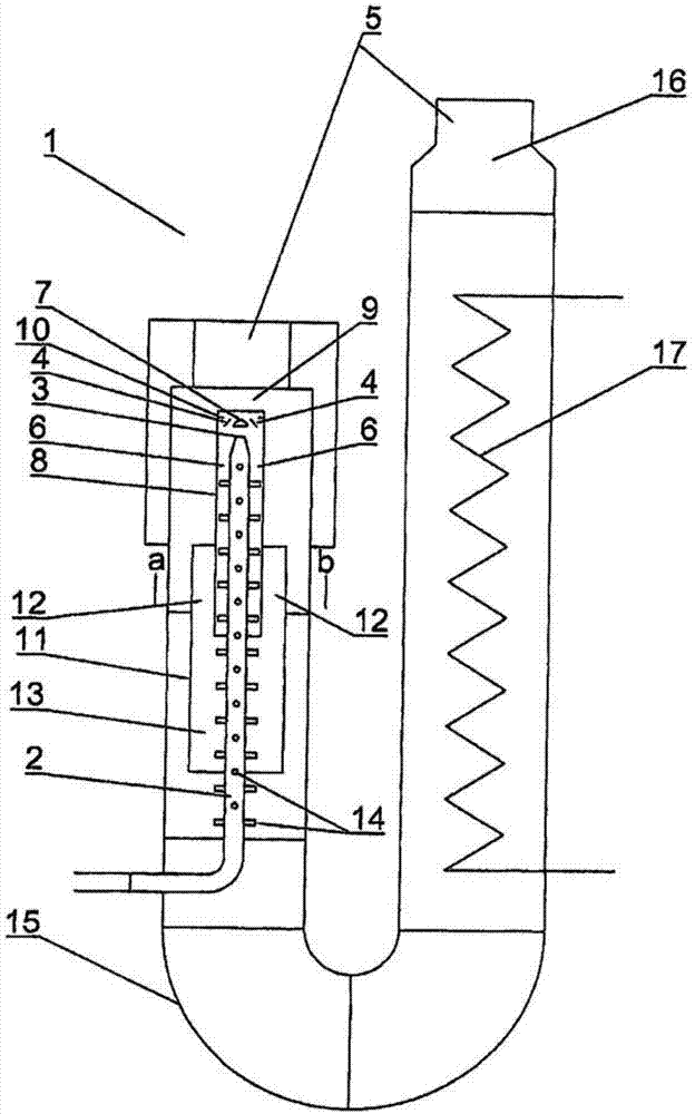
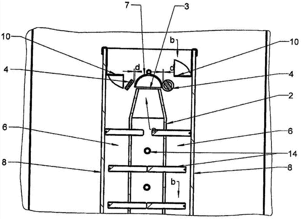
[0042] figure 1 with figure 2 An exemplary embodiment of a device 1 according to the invention for removing harmful gases, which are produced, for example, during the production of semiconductor materials, is shown. Hazardous gases of this type mainly include hydrogen and ammonia as process gases and other gases, especially metal-organic compounds that are incorporated into the process gas in smaller quantities. Furthermore, the process gas can additionally be mixed with nitrogen.

[0043] According to the invention, the conversion of the noxious gases into reaction gases which are subsequently combusted with air supply takes place by thermal cracking, wherein the heat generated during the combustion of the reaction gases is advantageously used for pyrolytic cracking of the noxious gases.

[0044] According to the invention, the device 1 has a heatable pyrolysis tube 2 through which harmful gases flow for thermal cracking. If harmful gases such as ammonia (NH 3 ), then th...


PUM


Abstract

The invention relates to a device (1) for disposing ammoniacal corrosive gases arising during manufacturing of semiconductor materials by combustion. The device (1) has a heatable pyrolysis tube (2), through which the corrosive gases flow through for thermal splitting into a reaction gas, an ignition device (4) downstream to an outlet (3) of the pyrolysis tube, and an air supply unit (5) for combustion of the reaction gas in a reaction zone (6). A deflection device (7) is arranged for deflection and entangling of the reaction gas with the supplied air based on the flow direction (a) of the corrosive gases in the pyrolysis tube downstream to the outlet of the pyrolysis tube.

Description

technical field [0001] The invention relates to a device for removing harmful gases by combustion, said device having: a heatable pyrolysis tube through which harmful gases flow for thermal cracking into reaction gases; an ignition downstream of the outlet of the pyrolysis tube means; and air supply means for the combustion of the reaction gas in the reaction zone. Background technique [0002] Hazardous gases in the sense mentioned here are particularly poisonous or other reactive gases which are also produced during the production of semiconductor materials, for example in the production of LEDs, and contain ammonia (NH 3 ), hydrogen (H 2 ) and sometimes nitrogen (N 2 ). This type of hazardous gas can be handled in different ways. One possibility for treating and converting reactive harmful gases is to oxidize or reduce these harmful gases by means of suitable oxidizing and reducing agents. Furthermore, those gases can be pyrolytically cracked thermally for subsequent...

Claims


Application Information

Patent Timeline
Patent Type & Authority Applications(China)
IPC IPC(8): F23G7/06
CPCF23C7/004F23C2900/03006F23G5/32F23G7/066F23D14/00F23D14/46F23G7/06
Inventor H·赖夏特A·弗伦策尔M·弗尔斯特C·克洛斯S·特雷普特R·维森贝格W·维森贝格G·戴维斯
Owner DAS ENVIRONMENTAL EXPERT
Why Eureka
Try Eureka