

Automatic measuring device for volume of grain pile and measuring method thereof
Patent Information
- Authority / Receiving Office
- CN · China
- Current Assignee / Owner
- INST OF REMOTE SENSING & DIGITAL EARTH CHINESE ACADEMY OF SCI
- Publication Date
- 2013-09-18
- Estimated Expiration
- Not applicable · inactive patent
Smart Images
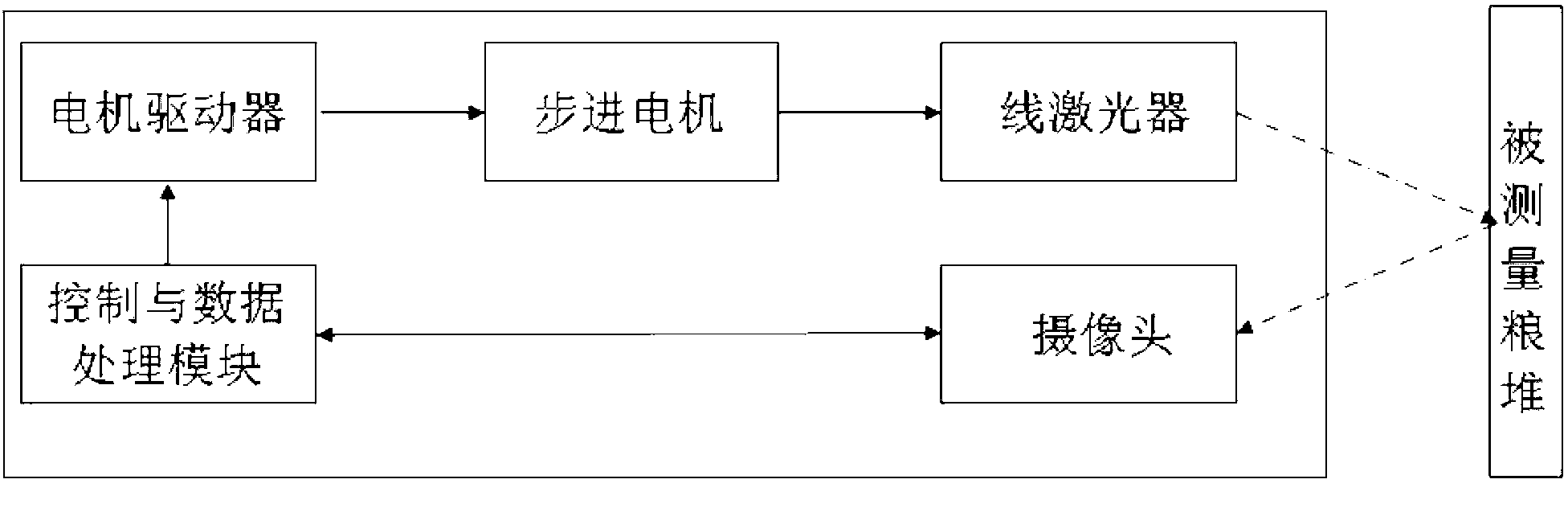
Figure 1 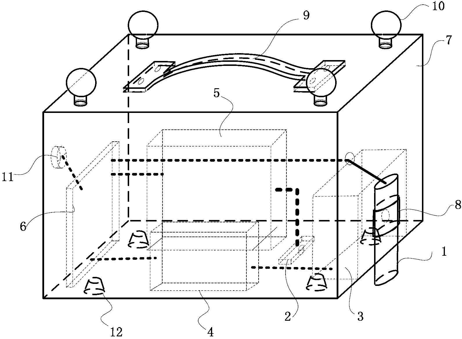
Figure 2 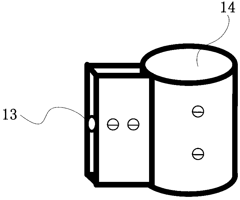
Figure 3
Abstract
Description
technical field
[0001] The invention relates to a device for automatically measuring the volume and a measuring method thereof, more particularly to a device for automatically measuring the volume of grain piles and a measuring method thereof, which are used in the field of grain quantity inventory supervision. Background technique
[0002] Grain is an important strategic material, and food security is related to the overall situation of China's economic development and social stability. The existing grain quantity inventory monitoring system is still not enough to provide reliable grain reserve information. China still needs to spend a lot of manpower and material resources to control the accurate quantity of grain reserves through the method of annual inventory clearance. In terms of efficiency, accuracy, cost and timeliness There are problems.
[0003] In terms of grain heap volume measurement, traditional methods generally use steel tapes and other length measuring tool...