

Pressure sensor chip
A pressure sensor and sensor technology, applied in the direction of measuring fluid pressure, instruments, and pressure difference measurement between multiple valves, to achieve the effect of ensuring pressure resistance and reducing stress
- Summary
- Abstract
- Description
- Claims
- Application Information
AI Technical Summary
Problems solved by technology
Method used
Image

Examples
Embodiment approach 1
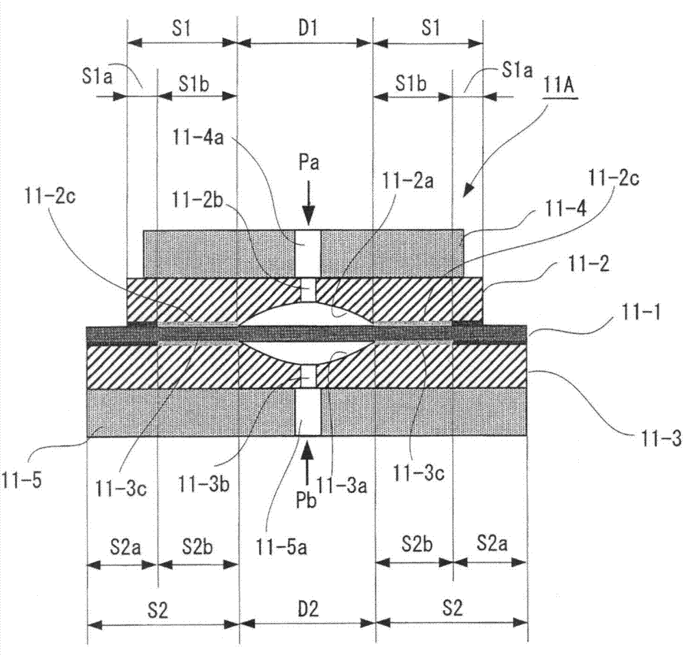
[0044] figure 1 It is a schematic diagram of an embodiment (Embodiment 1) of the pressure sensor chip of the present invention. In this figure, with Figure 10 same notation as with reference to Figure 10 The components described are the same or equivalent, and their descriptions are omitted. In addition, in this embodiment, the pressure sensor chip is denoted by symbol 11A to distinguish it from Figure 10 The pressure sensor chip 11 is shown.
[0045] In this pressure sensor chip 11A, among regions S1 where the peripheral portion 11-2c of the stopper member 11-2 faces one surface of the sensor diaphragm 11-1, the region S1a on the outer peripheral side is in contact with one surface of the sensor diaphragm 11-1. The region S1b on the inner peripheral side serves as a non-joint region that is not bonded to one surface of the sensor diaphragm 11-1. In addition, among the regions S2 where the peripheral portion 11-3c of the stopper member 11-3 faces the other surface of ...
Embodiment approach 2
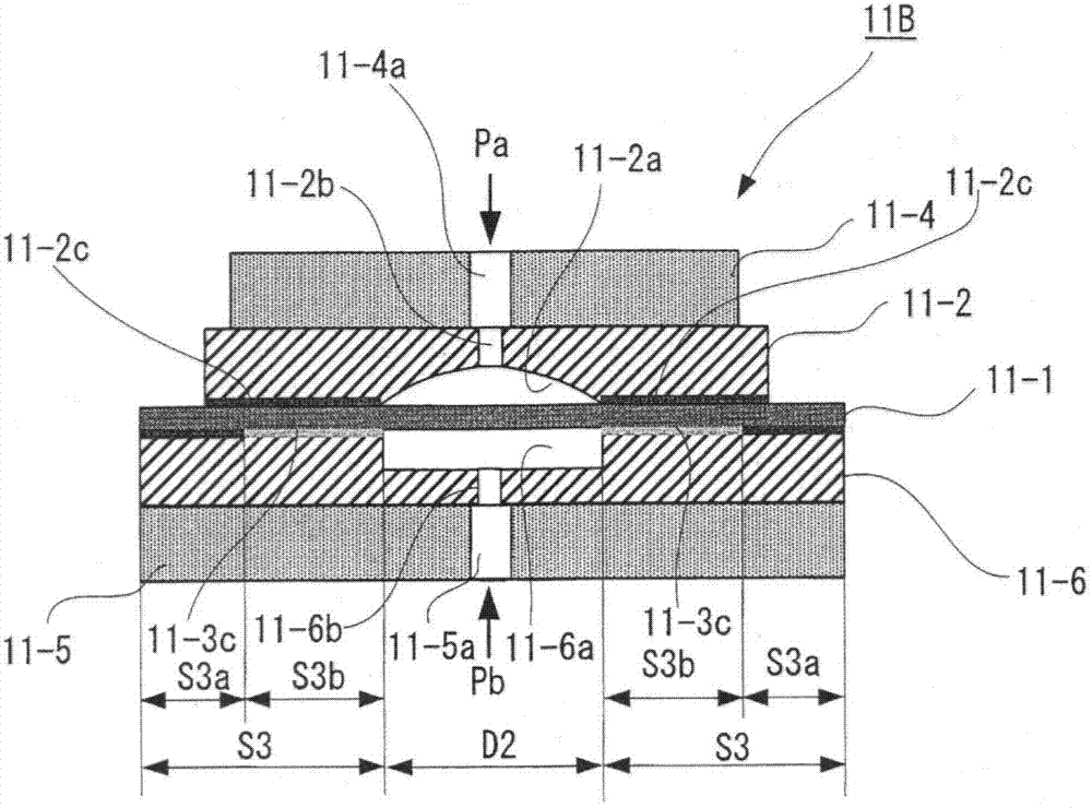
[0055] In Embodiment 1, the stopper members are provided on both surfaces of the sensor diaphragm 11-1, but if the surface of the sensor diaphragm 11-1 that receives the measurement pressure on the high-pressure side must be determined, the stopper members may be provided only on the side that receives the high-pressure side. A stopper member is provided on the surface opposite to the pressure measurement surface (the surface bearing the measurement pressure of the low pressure side), and only the holding member is provided on the surface bearing the measurement pressure of the high pressure side. The structure of this pressure sensor chip is in image 3 is shown as Embodiment 2 in .
[0056] In this pressure sensor chip 11B, the measured pressure Pb must be determined as the measured pressure on the high-pressure side, and the stopper member 11-2 is provided only on one surface of the sensor diaphragm 11-1 that bears the measured pressure Pa on the low-pressure side. Only th...
Embodiment approach 3
[0060]In Embodiment 1, stopper members are provided on both sides of the sensor diaphragm 11-1, but it is also possible to remove the excessive pressure protection function on both sides of the sensor diaphragm 11-1, and only provide a retaining member on both sides of the sensor diaphragm 11-1. member. The structure of this pressure sensor chip is in Figure 4 is shown as Embodiment 3 in .
[0061] On the pressure sensor chip 11C, a holding member 11-7 is provided on one surface of the sensor diaphragm 11-1, and a holding member 11-6 is provided on the other surface of the sensor diaphragm 11-1. That is, the recesses 11-6a, 11-7a of the holding members 11-6, 11-7 do not have curved surfaces along the displacement of the sensor diaphragm 11-1, and do not function as members for protecting against excessive pressure.
[0062] In addition, in this pressure sensor chip 11C, among the regions S3 where the peripheral portion 11-6c of the holding member 11-6 faces the other surfac...
PUM
 Abstract
Description
Claims
Application Information