
Wire branch connector

A technology of connectors and branches, applied in the direction of multi-conductor connectors, conductive connections, connections, etc., can solve the problems of easy natural loosening, unsafe electricity use, burning, etc., and achieve the effect of overcoming the connection of branch wires and the safety of electricity use

Inactive Publication Date: 2013-09-18
珠海市银雷极电科技有限公司
View PDF8 Cites 5 Cited by
  • Summary
  • Abstract
  • Description
  • Claims
  • Application Information

AI Technical Summary

Problems solved by technology

So far, for the connection of branch lines of power supply wires, especially in rural areas, whether it is indoor lines, outdoor lines, or main power lines, the connection method of the branch joints is to use the method of winding the branch line ends on the main line of the power supply and tightening them. Connection, this method can only maintain a good temporary conductive effect, but after a long time of use, the surface of the connection part will be slowly oxidized and corroded due to long-term sun and rain and long-term contact with air. At the same time, the wire ends wound on the main wire have the tension of their own weight, and are easy to loosen naturally. This leads to poor conduction of the connection parts for many reasons, resulting in unstable operation of electrical equipment, especially three-phase electric motors, which will be conductive due to wire joints. Bad and lack of phase, so that the three-phase electric motor is burned when it works under the working state of two-phase electricity. as a result of
Therefore, the prior art is a potential hidden danger of unsafe use of electricity to the method for connecting the branch joints of the power wires.

Method used


Image

  • Wire branch connector
  • Wire branch connector
  • Wire branch connector

Examples


Embodiment Construction

[0016] The present invention will be further described below in conjunction with the accompanying drawings and embodiments and its use and operation.

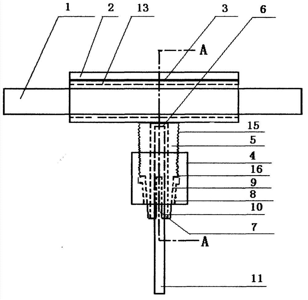
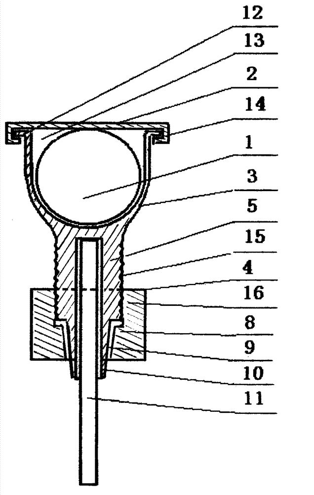
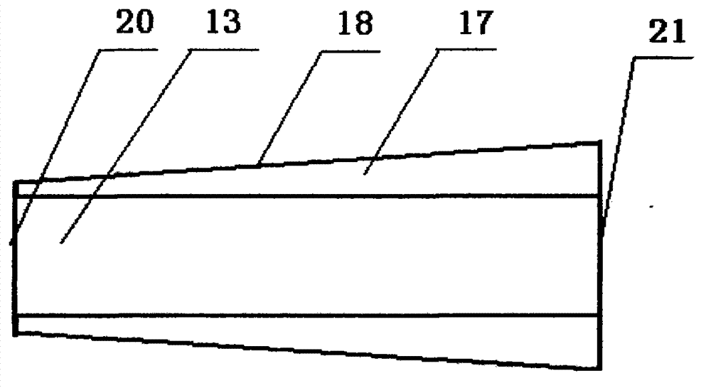
[0017] In the figure: the wire clip (3) and the branch rod (5) form a T-shaped conductive whole, the wire clip part is composed of the wire clip (3) and the wire clip cover (2), and the branch line is formed by the branch rod (5) ), a tightening nut (4); there is a U-shaped long slot (13) for embedded power supply main wire in the clip (3), and there is a symmetrical one with a large head and a small tail on both sides of the U-shaped long slot opening. 7-shaped curved plane (17); the clamp cover (2) cover surface becomes a decent shape ( Figure 4 ), the angles of its four corners are equal to the angles of the four corners of the 7-shaped curved plane (17) on both sides of the U-shaped long groove of the wire clip clip, and a hook-shaped groove (14) is respectively arranged below the two sides; the wire clip plane ( image 3...


PUM


Abstract

The invention discloses a wire branch connector, which comprises a wire clamp, a wire clamp cover, a branch rod and a wire tightening nut. The wire branch connector is characterized in that the wire clamp and the branch rod are in a T-shaped electricity conduction whole; the wire clamp is internally provided with a U-shaped long slot used for embedding main power source conduction wires; fixed connection of the main power source conduction wires is formed by the wire clamp cover; a branch circuit is fixedly connected with the branch rod, a branch rod inner hole, a branch rod cone and a cone clamp piece through the wire tightening nut in a screwing manner. With the adoption of the wire branch connector, the branch conduction wires can be connected on the main power source conduction wires conveniently and fast; the connection part can be guaranteed to be used for a long time; and good electrical conductivity can be well kept, so that the purpose of power utilization safety can be achieved.

Description

Technical field [0001] The invention relates to a branch connection fitting for a power supply wire, which belongs to a supporting component in the field of electric power. Background technique [0002] The so-called wire branch connection is to add a new line from the power pole line, or be called the main power line or the main line. So far, for the connection of branch lines of power supply wires, especially in rural areas, whether it is indoor lines, outdoor lines, or main power lines, the connection method of the branch joints is to use the method of winding the branch line ends on the main line of the power supply and tightening them. Connection, this method can only maintain a good temporary conductive effect, but after a long time of use, the surface of the connection part will be slowly oxidized and corroded due to long-term sun and rain and long-term contact with air. At the same time, the wire ends wound on the main wire have the tension of their own weight, and ...

Claims


Application Information

Patent Timeline
Patent Type & Authority Applications(China)
IPC IPC(8): H01R11/01H01R11/05H01R4/50
Inventor 占行波
Owner 珠海市银雷极电科技有限公司
Learn More