Synchronous belt driving type full tracked robot
A crawler robot and synchronous belt drive technology, applied in tracked vehicles, motor vehicles, transportation and packaging, etc., can solve problems such as stuck, unable to meet the use requirements, increase the weight of mobile robots, etc., to achieve high maneuverability and good stability Effect
- Summary
- Abstract
- Description
- Claims
- Application Information
AI Technical Summary
Problems solved by technology
Method used
Image

Examples
Embodiment 1
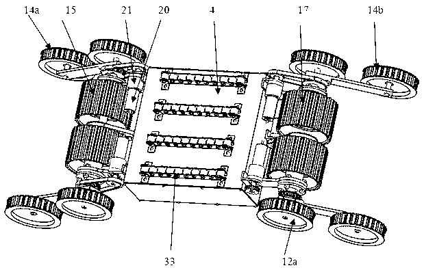
[0028] 1. see figure 1 , the synchronous belt driven full track robot, including two independently driven main track devices 1-A, 1-B, four independently driven swing arm devices 2-A, 2-B, 2-C, 2-D , four supporting structures 3-A, 3-B, 3-C, 3-D, one rack 4, etc. The two independently driven main crawler devices 1-A, 1-B are identical and are installed parallel and side by side on the frame 4, so that the crawlers completely wrap the robot body with the frame 4 as the main body. , the four independently driven swing arm devices 2-A, 2-B, 2-C, 2-D are respectively installed by the four supporting mechanisms 3-A, 3-B, 3-C, 3-D At the four corners of the frame 4; the two main crawler devices 1-A, 1-B realize the moving and walking of the robot; ; Four independently driven swing arm devices 2-A, 2-B, 2-C, and 2-D are used to realize the robot's multi-pose adaptation to terrain and landform problems.
Embodiment 2
[0029] Embodiment 2: This embodiment is basically the same as Embodiment 1, and the special features are as follows:
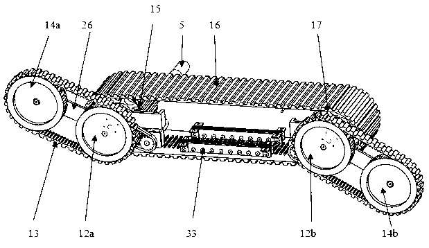
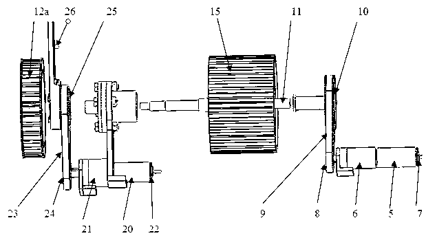
[0030] The above two independently driven main crawlers 1-A and 1-B are identical, as figure 2Shown, all are by main drive motor 5, final reducer 6, main encoder 7, main small synchronous belt pulley 8, main synchronous belt 9, main large synchronous belt pulley 10, driving main shaft 11, rear swing arm wheel 12a and 12b, swing arm rubber track 13, front swing arm wheels 14a and 14b, driving wheel 15, main rubber track 16, driven wheel 17, passive main shaft 18 and the like. The final reducer 6 is connected to the frame middle plate 19 by bolts, such as Figure 7 As shown, and the main reducer 6 is arranged outside the following main rubber crawler 16; the main drive motor 5 is connected to the main reducer 6 through a double-ended stud, and the main encoder 7 is connected to the main drive motor 5 through a double-ended stud; the main small synchronous The...
Embodiment 3
[0034] Embodiment 3: This embodiment is basically the same as Embodiment 1, and the special features are as follows:
[0035] The above-mentioned main drive motors 5 are two in total and identical, symmetrically distributed on the outside of the frame 4 front and rear and installed on the frame middle plate 19 in the opposite direction; four swing arm drive motors 20 are identical, symmetrically arranged in the frame opposite to each other in front, rear, left, and right 4 outside and installed on the frame side plate 28;
PUM
 Abstract
Description
Claims
Application Information
 - R&D
- Intellectual Property
- Life Sciences
- Materials
- Tech Scout
- Unparalleled Data Quality
- Higher Quality Content
- 60% Fewer Hallucinations
Browse by: Latest US Patents, China's latest patents, Technical Efficacy Thesaurus, Application Domain, Technology Topic, Popular Technical Reports.
© 2025 PatSnap. All rights reserved.Legal|Privacy policy|Modern Slavery Act Transparency Statement|Sitemap|About US| Contact US: help@patsnap.com