Rotation-free pawl-type sliding sleeve with ball seat capable of being taken out

A technology of ball seat and sliding sleeve, which is applied in the direction of production fluid, wellbore/well components, earthwork drilling and production, etc. It can solve the problems of pipe string fishing failure, easy jamming, and non-rotating pipe string running, etc., to achieve The effect of simple equipment and low salvage cost

Inactive Publication Date: 2013-09-25
CNPC BOHAI DRILLING ENG
View PDF6 Cites 20 Cited by
  • Summary
  • Abstract
  • Description
  • Claims
  • Application Information

AI Technical Summary

Problems solved by technology

At present, the commonly used salvage method is threaded fishing, which needs to rotate the fishing tool to complete the threaded connection during the salvage process, so this type of invention cannot be run in non-rotating strings such as coiled tubing and steel wires.
In addition, there are many components of the ball seat in the existing fishable sliding sleeve, and the risk of jamming is prone to occur during the fishing process, which leads to the failure of the whole trip of the pipe string

Method used


Image

  • Rotation-free pawl-type sliding sleeve with ball seat capable of being taken out
  • Rotation-free pawl-type sliding sleeve with ball seat capable of being taken out
  • Rotation-free pawl-type sliding sleeve with ball seat capable of being taken out

Examples


Embodiment Construction

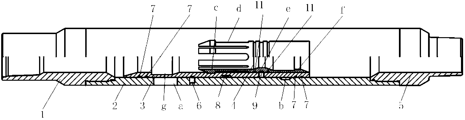
[0020] The structure of the one-pass rotation-free ratchet type removable ball seat sliding sleeve of the present invention will be described in detail below in conjunction with the accompanying drawings.

[0021] see figure 1 , the one-turn non-rotating pawl-type removable ball seat sliding sleeve includes: a sliding sleeve body composed of an upper joint 1, an outer cylinder 2 and a lower joint 5 that are sequentially threaded, an inner sliding sleeve installed in the outer cylinder 2, and an inner sleeve installed in the outer cylinder 2. The ball seat cylinder in the inner sliding sleeve. The sliding sleeve body and the inner sliding sleeve 3 are fixed by shear nails 6, and the inner sliding sleeve and the ball seat cylinder are fixed by shear nails 9. The two ends of the inner sliding sleeve and the main body of the sliding sleeve are sealed by sealing rings 7, and there are two sealing rings 7 at both ends of the inner sliding sleeve.

[0022] A liquid outlet hole a is...


PUM


Abstract

The invention discloses a rotation-free pawl-type sliding sleeve with a ball seat capable of being taken out. The sliding sleeve comprises a sliding sleeve body, an inner sliding sleeve and a ball seat cylinder, wherein the sliding sleeve body is composed of an upper connector, an outer cylinder and a lower connector. The sliding sleeve body and the inner sliding sleeve are fixed through a shear nail, the inner sliding sleeve and the ball seat cylinder are fixed through a shear nail, a fluid outlet hole is formed in the upper portion of the outer cylinder, and a clamping spring hole is formed in the lower position of the middle of the inner wall of the outer cylinder. An annular switch clamping groove is formed in the inner wall of the upper portion of the inner sliding sleeve, a plurality of split pawl clamping grooves are formed in the inner wall of the middle of the inner sliding sleeve in the peripheral direction, and a clamping spring is installed on the outer wall of the middle of the inner sliding sleeve. A plurality of male pawls are arranged at the upper end of the ball seat cylinder in the peripheral direction, a plurality of female pawls are arranged on the inner side of the lower end of the ball seat cylinder in the peripheral direction, the male pawls are clamped into the split pawl clamping grooves, and a variable diameter ball seat is arranged in the ball seat cylinder. When the inner sliding sleeve moves to the lower end of the outer cylinder, the clamping spring on the inner sliding sleeve is clamped into the clamping spring hole in the outer cylinder. All base seat cylinders can be salvaged through non-rotating type tubular columns in a disposable mode, and a full through path is achieved.

Description

technical field [0001] The invention relates to the technical field of oil and gas field exploitation, in particular to a one-pass rotation-free ratchet-type removable ball seat sliding sleeve for supporting the staged fracturing technology Background technique [0002] At present, the multi-stage fracturing reconstruction of horizontal wells in oil and gas fields generally adopts oil layer special drilling technology and hanging packers, sliding sleeves, open hole packers and supporting tools to realize multi-stage fracturing, or uses cementing sliding sleeves and supporting tools for cementing. Multistage fracturing. Horizontal well staged fracturing sleeves include ball-throwing sleeves and differential pressure opening sleeves. The ball-throwing sleeve technology is to open the sliding sleeve of the fracturing switch by throwing low-density balls, exposing the communication hole between the oil layer and the tubing, and connecting Oil pipe and oil layer. Compared with ...

Claims


Application Information

Patent Timeline
Patent Type & Authority Applications(China)
IPC IPC(8): E21B34/06E21B43/26
Inventor 冯强王瑶郭鸣程智远何志勇
Owner CNPC BOHAI DRILLING ENG
Why Eureka
Try Eureka