

Relay flow fan and extractor hood with same
A technology of flow fan and cross-flow fan, applied in the field of range hood, can solve the problems of reducing air volume, reducing fan efficiency, separating and purifying difficult oil molecules, etc., and achieving the effect of long air supply distance, wide application and large air volume
- Summary
- Abstract
- Description
- Claims
- Application Information
AI Technical Summary
Problems solved by technology
Method used
Image

Examples
Embodiment 1
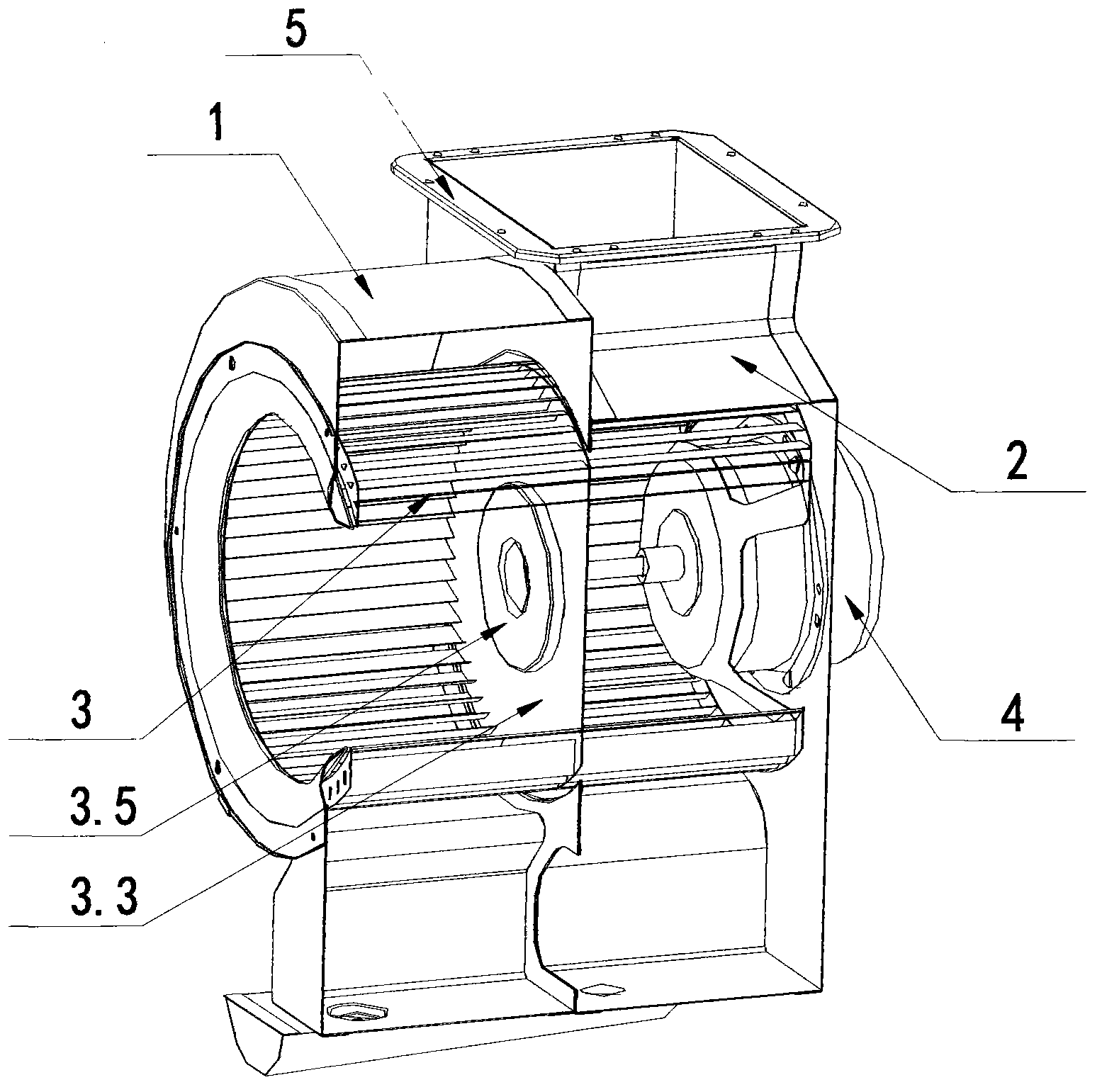
[0058] like Figure 1~6 As shown, the relay flow fan of this embodiment is composed of a centrifugal fan 1 and a cross-flow fan 2 connected in series. The air outlet of the centrifugal fan is connected with the air inlet of the cross-flow fan. The impeller 3, the same motor 4, and the same volute assembly 5.
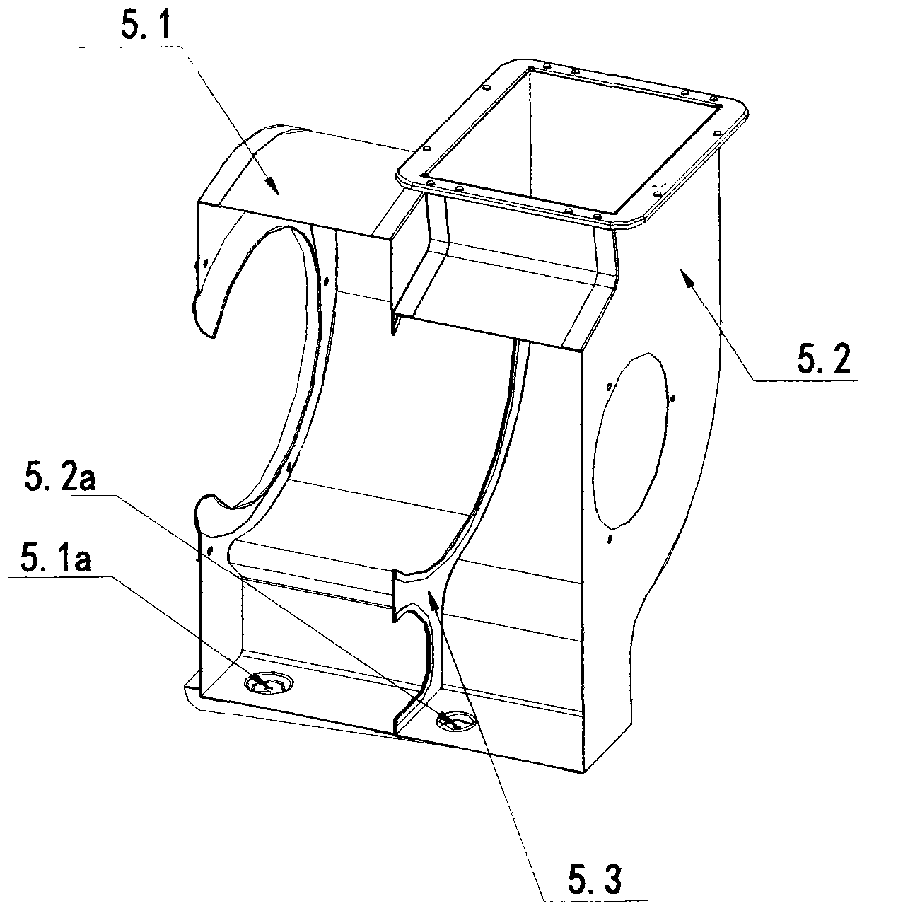
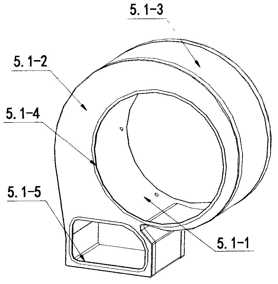
[0059] The volute assembly 5 includes at least a centrifugal fan volute 5.1 and a cross-flow fan volute 5.2, which is composed of a centrifugal fan volute and a cross-flow fan volute connected in parallel. The centrifugal fan volute is placed at the front end of the cross-flow fan volute, and the cross-flow fan volute The shell is provided with a motor installation structure. The centrifugal fan volute is composed of a front cover 5.1-1, a rear cover 5.1-2, and a volute wall 5.1-3. The rear cover is provided with an opening 5.1-4 suitable for the rotation of the impeller, and is provided with a centrifugal fan outlet. The opening connecting the channel and the inlet ch...
Embodiment 2
[0062] This embodiment and embodiment 1 belong to the typical structure of the first technical solution of the present invention, such as Figure 7-12 As shown, the only difference between this embodiment and Embodiment 1 is that the structure and shape of the volute assembly are different, the shape of the construction hole plugging cover used on the dual-function impeller and the length of the motor shaft are different.
[0063] In the volute assembly in this embodiment, the front cover 5.1-1 of the centrifugal fan volute and the volute wall 5.1-3 are integrated to form an integral centrifugal fan volute main body 5.1A, and a mounting edge 5.1A is provided around it -1; the back cover 5.2-2 of the volute of the cross-flow fan is integrated with the volute wall 5.2-3 to form an integral cross-flow volute main body 5.2A, and its periphery is also provided with a mounting edge 5.2A-1; Between the volute main body of the type centrifugal fan and the volute main body of the integ...
Embodiment 3
[0068] like Figures 13 to 16 As shown, the relay flow fan of this embodiment is composed of a centrifugal fan 1 and a cross-flow fan 2 connected in series, the air outlet of the centrifugal fan communicates with the air inlet of the cross-flow fan, and the centrifugal fan and the cross-flow fan are of a connected structure. The impeller, motor, and volute assembly; the air inlet channel of the cross-flow fan is closed.
[0069] The volute assembly of the centrifugal fan at least includes a front cover 5.1-1, a rear cover 5.1-2, and a volute wall 5.1-3, and an air outlet 5.1-3a is provided on the plane section of the volute wall corresponding to the outlet channel of the centrifugal fan ; The volute assembly of the cross-flow fan includes at least the left end cover 5.2-1, the right end cover 5.2-2, and the volute wall 5.2-3. The air inlet 5.2-3a is provided on the corresponding volute wall plane section; the flanging riveting structure 5.3-3 is provided at the air outlet 5.1...
PUM
 Abstract
Description
Claims
Application Information