A water level automatic control float valve

A floating ball valve, water level technology, applied in the direction of lift valve, valve details, valve device, etc., can solve the problems of water accumulation in the water tank, dust endangering the health of operators, increasing the use of mines and saving capital, etc., to achieve the effect of reliable and safe use

Active Publication Date: 2015-11-04
CHINA COAL TECH & ENG GRP CHONGQING RES INST CO LTD
View PDF6 Cites 0 Cited by
  • Summary
  • Abstract
  • Description
  • Claims
  • Application Information

AI Technical Summary

Problems solved by technology

[0002] Dust-producing places such as mine mining, roadway excavation, tunnel excavation, material transportation, etc., especially roadway excavation, fully-mechanized mining face return airway, anchor shotcrete operation return air side, solid material transportation reload point, fixed-point dust source, etc. The generation of a large amount of dust endangers the health of the workers. The current dust reduction measures basically adopt high-pressure spraying to reduce dust, and the key equipment water tank involved in the high-pressure spray dust reduction system, because the float valve in the prior art is suitable for water pressure ≤ 2Mpa , but at present the vertical height of most coal mines from the coal mining face to the ground surface is more than 300m, and the natural pressure of the underground water supply reaches more than 3MPa, so the existing float valve cannot close the water source at all, resulting in water accumulation everywhere around the water tank. Serious waste of water resources
Or, remove the float valve and directly control the water level manually. Therefore, when using high-pressure spray, it is necessary to send a special person to guard the water tank, which virtually increases the cost of the mine.

Method used


Image

  • A water level automatic control float valve
  • A water level automatic control float valve
  • A water level automatic control float valve

Examples


Embodiment Construction

[0026] Below in conjunction with accompanying drawing and embodiment the present invention will be further described:

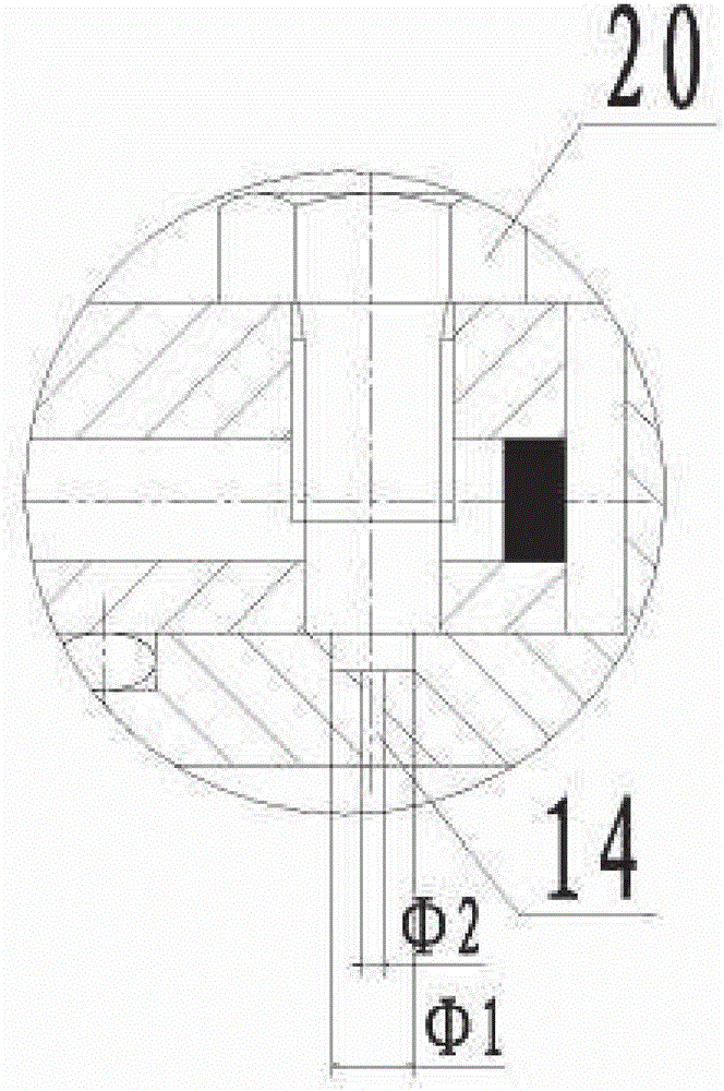
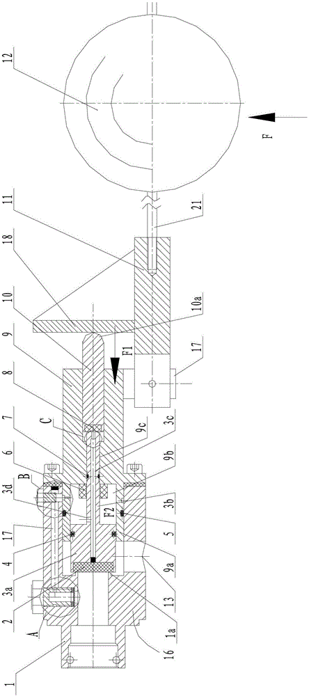
[0027] like Figure 1 to Figure 4 As shown, a float valve with automatic water level control includes a valve body 16, on which a water inlet 1 and a water outlet 13 intersecting each other are arranged, and a flange 1a is arranged at the end of the water inlet 1.

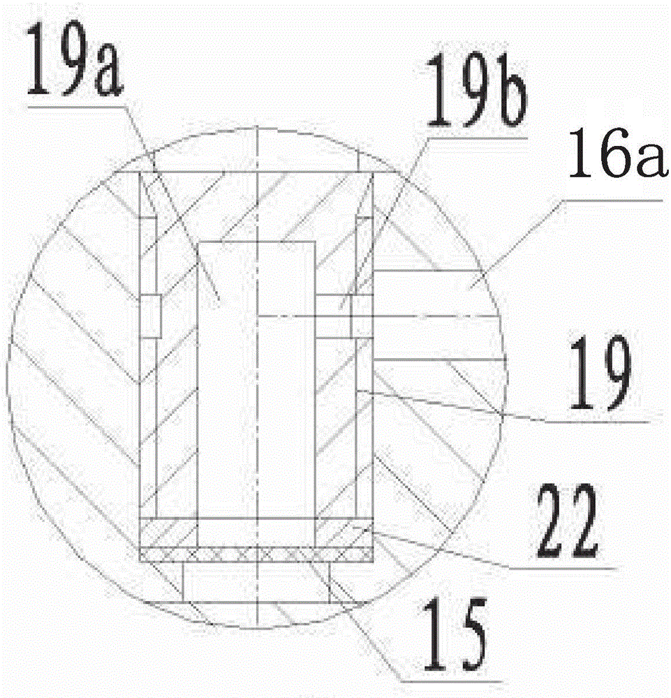
[0028] Valve body 16 is fixed with piston seat 9 relative to the far end of water inlet 1, and one end of piston seat 9 stretches in the valve body 16, and this protruding end 9a is set as piston chamber 9b, is provided with piston body 3a in piston chamber 9b, and piston The end surface of the body 3a can block the water inlet 1, and the cylindrical surface can block the water outlet 13. The bottom of the piston chamber 9b is fixed with a limit sleeve 6 .

[0029] The valve body 16 is provided with a flow channel 16a which can communicate with the water inlet 1 and the piston cavity 9b, and the...


PUM


Abstract

The invention discloses an automatic water level control float valve comprising a valve body. A water inlet and a water outlet are formed in the valve body. A piston seat is fixed at the far end, relative to the water inlet, of the valve body. One end of the piston seat extends into the valve body and is provided with a piston cavity. A piston is arranged in the piston cavity. A flow passage capable of communicating the water inlet with the piston cavity is formed in the valve body. A through hole corresponding to the flow passage is formed at the extending end of the piston seat. An axial through hole concentric with the piston cavity is arranged on the piston seat. A piston rod is arranged at the tail of the piston integrally and extends into the axial through hole. A moving piston which can be sealed with the end face of the piston rod is arranged at the other end of the axial through hole. A piston rod shaft hole with one end communicating with the axial through hole is formed in the piston rod. A support is fixed on the lower portion of the piston seat. A push rod is hinged on the support. A push plate opposite to the moving piston is fixed on the push rod. The automatic water level control float valve can control water level of a water tank automatically, is reliable and safe to use, and can resist pressure above 40MPa.

Description

technical field [0001] The invention relates to a valve for controlling the water level of a water tank. Background technique [0002] Dust-producing places such as mine mining, roadway excavation, tunnel excavation, material transportation, etc., especially roadway excavation, fully-mechanized mining face return airway, anchor shotcrete operation return air side, solid material transportation reload point, fixed-point dust source, etc. The generation of a large amount of dust endangers the health of the workers. The current dust reduction measures basically adopt high-pressure spraying to reduce dust, and the key equipment water tank involved in the high-pressure spray dust reduction system, because the float valve in the prior art is suitable for water pressure ≤ 2Mpa , but at present the vertical height of most coal mines from the coal mining face to the ground surface is more than 300m, and the natural pressure of the underground water supply reaches more than 3MPa, so t...

Claims


Application Information

Patent Timeline
Patent Type & Authority Patents(China)
IPC IPC(8): F16K1/32F16K1/36F16K27/02F16K31/22
Inventor 张少华隋金君黄金星张小涛包亮王军张平黄立宁崔秀伟
Owner CHINA COAL TECH & ENG GRP CHONGQING RES INST CO LTD
Why Eureka
Try Eureka