Low-temperature gas cylinder vacuuming system

A vacuum pumping system and vacuum pumping technology, which is applied to fixed-capacity gas storage tanks, gas/liquid distribution and storage, pressure vessels, etc., can solve the problems of long pumping time, increased vacuum resistance, and differences in the vacuum degree of gas cylinders Large and other problems, to achieve the effect of improving vacuum efficiency, shortening length, and improving conductance

Inactive Publication Date: 2013-09-25
ZHANGJIAGANG FURUI SPECIAL EQUIP CO LTD
View PDF6 Cites 6 Cited by
  • Summary
  • Abstract
  • Description
  • Claims
  • Application Information

AI Technical Summary

Problems solved by technology

The branch pipe needs to use bellows to facilitate the connection with the cylinder to be evacuated and can withstand high temperature and shock. However, due to the long length of the bellows branch pipe, it not only increases the vacuum resistance but also has a great influence on the conductance of the vacuum, causing the cylinder It takes a long

Method used


Image

  • Low-temperature gas cylinder vacuuming system
  • Low-temperature gas cylinder vacuuming system
  • Low-temperature gas cylinder vacuuming system

Examples


Embodiment Construction

[0015] Specific embodiments of the present invention will be described in detail below in conjunction with the accompanying drawings.

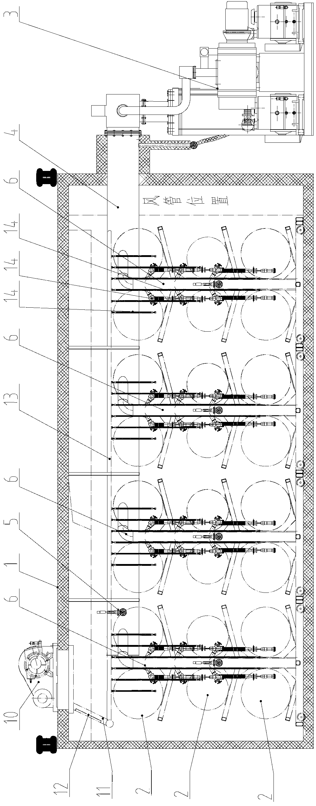
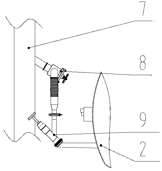
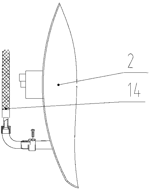
[0016] like Figure 1-3 As shown, the low-temperature gas cylinder vacuum system includes a body of furnace 1, a number of cylinders to be evacuated 2 arranged in the inner cavity of the body of furnace 1, and a vacuum unit 3 connected to the cylinder 2 to be evacuated. It is connected with the main pipe 4, and the main pipe 4 is provided with a vacuum gauge 5. The main pipe 4 is provided with 8 primary branch pipes 6, and each primary branch pipe 6 is provided with 6 secondary branch pipes 7, and the secondary branch pipes 7 are bellows. The secondary branch pipe 7 is connected to the vacuum port of the cylinder 2 to be pumped through the baffle valve 8 and the vacuum tooling 9 .

[0017] The system also includes a heating device inside the gas cylinder, including a blower 10 arranged on the furnace body 1 , the air outlet of the blower 10 ...


PUM


Abstract

The invention discloses a low-temperature gas cylinder vacuuming system comprising a furnace body, a plurality of gas cylinder to be pumped arranged in the inner cavity of the furnace, and a vacuuming set communicating with the gas cylinders to be pumped. The vacuuming set is connected with a main pipe. A plurality of primary branch pipes are arranged on the main pipe. A plurality of secondary branch pipes are arranged on the primary branch pipes. The secondary branch pipes are corrugated pipes and are connected with the vacuuming ports of the gas cylinder to be pumped. The low-temperature gas cylinder vacuuming system provided by the invention has the advantages of high efficiency and good vacuuming effect.

Description

technical field [0001] The invention relates to a low-temperature gas cylinder vacuum pumping system. Background technique [0002] The vacuum pipeline system is a pipeline system that connects the evacuation unit with the evacuation port of the LNG vehicle bottle. The vacuuming capacity of the evacuation unit is used to evacuate the interlayer of the gas cylinder to meet the requirements of vacuum insulation. The pipeline system in the original vacuum system equipment uses a single main pipe to connect from the vacuum unit to the vacuum furnace, and directly leads multiple branch pipes from the main pipe to connect to the vacuum port of the gas cylinder for vacuuming. The branch pipe needs to use bellows to facilitate the connection with the cylinder to be evacuated and can withstand high temperature and shock. However, due to the long length of the bellows branch pipe, it not only increases the vacuum resistance but also has a great influence on the conductance of the vacu...

Claims


Application Information

Patent Timeline
IPC IPC(8): F17C1/12
Inventor 邱芳许云龙童杰东许春华钱志浩
Owner ZHANGJIAGANG FURUI SPECIAL EQUIP CO LTD
Why Eureka
Try Eureka