Knuckle bearing detection device

A technology of joint bearing and detection device, which is applied in the direction of mechanical bearing testing, etc., can solve problems such as inability to accurately evaluate the quality of fixation

Active Publication Date: 2013-09-25
COMAC +1
View PDF7 Cites 9 Cited by
  • Summary
  • Abstract
  • Description
  • Claims
  • Application Information

AI Technical Summary

Problems solved by technology

However, in the actual use process, the axial load borne by most joint bearings changes with time in value and direction, taking into account the release of the residual stress generated during the bearing manufacturing process and the installation process during use. Due to factors such as the influence of the fixed quality of the bearing, the existing one-time push-out detection method cannot accurately evaluate the fixed quality of the joint bearing under the actual load.

Method used


Image

  • Knuckle bearing detection device
  • Knuckle bearing detection device

Examples


Embodiment Construction

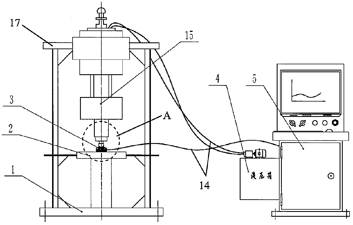
[0020] The joint bearing detection device implementing the present invention will be described in detail below, first referring to figure 1 , which shows a schematic structural diagram of a joint bearing detection device according to an embodiment of the present invention. The joint bearing testing device includes a testing table 2 , the testing table 2 can be placed on a support base 1 , and a joint bearing clamping device 3 for clamping the joint bearing is fixed on the testing table 2 . The loading system is arranged above the joint bearing clamping device 3, and includes a loading head, a hydraulic actuation system, and a tension and pressure sensor arranged between the loading head and the hydraulic actuation system, which will be described in detail below. The hydraulic actuating system can be supported by a bracket 17 provided on the support base 1, and is connected with the hydraulic controller part 4 in the control system through wires, so as to realize actuation cont...


PUM


Abstract

A knuckle bearing detection device comprises a detection workbench, a knuckle bearing clamping device mounted on the detection workbench, a loading system and a control system. The knuckle bearing clamping device comprises a knuckle bearing fixing seat and a knuckle bearing fixing cover which are respectively provided with a central hole. The loading system comprises a loading head, a hydraulic action system used for driving the loading head, and a pull pressure sensor arranged between the loading head and the hydraulic action system. The detection device further comprises a knuckle bearing outer ring fixing piece used for fixing the outer ring of a knuckle bearing on the loading head and a displacement sensor which is mounted on the detection workbench and is opposite to the knuckle bearing outer ring fixing piece. The control system carries out signal collecting and processing on the pull pressure sensor and the displacement sensor and controls the loading system according to collected signals. The detection device can accurately and reliably detect the fixing quality of the knuckle bearing under the action of actual loads and detect the needed axial loads for generating set displacement by the knuckle bearing.

Description

technical field [0001] The invention belongs to the technical field of engineering machinery testing equipment, and relates to a detection device for a joint bearing. Background technique [0002] The spherical plain bearing is a sliding bearing with a special structure, which is mainly composed of an inner ring with an outer spherical surface and an outer race with an inner spherical surface. The performance of the joint bearing in the free state is quite different from that of the joint bearing in the working state, and the actual performance of the joint bearing can only be shown after the assembly is completed. Therefore, the current value of the push-out force is mainly used to judge whether the fixation of the spherical plain bearing is reliable, so as to evaluate the fixed quality of the spherical plain bearing. [0003] There are two existing push-out force detection methods: one is to detect the maximum push-out force by pushing out at one time; the other is to app...

Claims


Application Information

Patent Timeline
Patent Type & Authority Applications(China)
IPC IPC(8): G01M13/04
Inventor 郭超行杨育林李明仁王礼嘉胡占齐齐效文李传海范兵利
Owner COMAC
Why Eureka
Try Eureka