Cable connector fault diagnosing method

A cable joint and fault diagnosis technology, applied in the direction of measuring electricity, measuring electrical variables, instruments, etc., can solve the problems of limited application scope, failure to consider the transient process of cable heat capacity and temperature rise of cable joints, etc.

Inactive Publication Date: 2013-09-25
WUHAN UNIV
View PDF6 Cites 43 Cited by
  • Summary
  • Abstract
  • Description
  • Claims
  • Application Information

AI Technical Summary

Problems solved by technology

[0008] The above simplified model fails to take into account the heat capacity of the cable and the transient process of the temperature rise of the cable joint. It is only suitable for the situation where the ambient temperature is relatively stable, the cable is loaded with a stable load and lasts for a long time to reach thermal equilibrium, which greatly limits its application range.

Method used

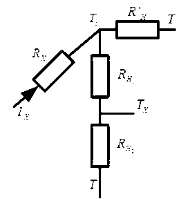
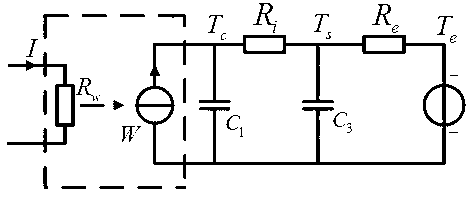
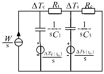

Image

  • Cable connector fault diagnosing method
  • Cable connector fault diagnosing method
  • Cable connector fault diagnosing method

Examples


Embodiment Construction

[0086] Below by embodiment, in conjunction with accompanying drawing, technical scheme of the present invention is described further in detail:

[0087] Step 1: Initialize the system conditions: ①Set the inner aluminum sheath of the cable joint as the monitoring point of the joint temperature, and set the outer surface temperature of the cable joint as the monitoring point of the ambient temperature ②Set the maximum fluctuation threshold m=0.2℃ in the steady state of the ambient temperature , The maximum fluctuation threshold n=50A when the cable current is in a steady state; ③Set the minimum time unit t during monitoring x =1min, the sampling interval Δt of the independent variable and the dependent variable m =11min;

[0088] Step 2: Press the set t x , real-time sampling of cable current I and monitoring point temperature T at equal intervals s and ambient temperature T e , and save the historical monitoring data to form I, T s , T e The monitoring curve about the tim...


PUM


Abstract

The invention provides a cable connector fault diagnosing method. The cable connector fault diagnosing method comprises the steps that the temperature of the outer surface of a cable connector and the temperature of a monitoring point (located at the zero potential position of the outer surface of an aluminum protective sleeve or the outer surface of a prefabricated rubber insulating layer) inside the cable connector are monitored in real time; the linear least squares method is used for identifying relevant parameters of cable connector transient state thermal circuit models through the temperatures obtained through real-time monitoring in order to obtain the time constant tau of the first order transient state thermal circuit model and the steady state temperature rise coefficient k of the first order transient state thermal circuit model; and fault diagnose is conducted on the cable connector by the utilization of the identifying result. By means of the cable connector fault diagnosing method, the four common faults of the cable connector can be effectively diagnosed, the defect that in many quality evaluating theories of simplified models, cable heat capacity and the transient state process of cable connector temperature rise are not considered is overcome, the demand for on-line fault monitoring of the cable connector is met, and the stability of system running is improved.

Description

technical field [0001] The invention relates to the field of power cable lines in power transmission and distribution systems, in particular to a cable joint fault diagnosis method. Background technique [0002] In the power supply system of cities and large and medium-sized enterprises, more and more power cables are used for power transmission and distribution. Years of operating experience and analysis of accidents show that more than 90% of cable failures occur at the cable joints. When there are quality problems such as increased contact resistance at the joint, its operating temperature will increase accordingly, thereby accelerating the insulation aging at the joint and increasing the probability of partial discharge, forming a vicious circle, and even causing cable fires in severe cases. If the cable joint can be monitored online and the accurate temperature of the wire core can be grasped in real time, the change of the quality of the joint can be detected in time ...

Claims


Application Information

Patent Timeline
Patent Type & Authority Applications(China)
IPC IPC(8): G01R31/00G01K13/00
Inventor 谭甜源高云鹏阮江军常辉樊润荣刘开培肖微乐健刘剑
Owner WUHAN UNIV
Why Eureka
Try Eureka