
Method determining controllable vibration source best low-frequency scanning signal

A scanning signal and source technology, which is applied in the field of terrestrial vibroseis scanning signal design in seismic exploration, can solve the problem that the low-frequency exploration performance of the source cannot achieve better results, and the flow limit of the vibroseis without comprehensive consideration of the vibrator weight stroke cannot be obtained. Problems with scanning signals, etc.

Active Publication Date: 2013-09-25
BC P INC CHINA NAT PETROLEUM CORP +1
View PDF6 Cites 21 Cited by
  • Summary
  • Abstract
  • Description
  • Claims
  • Application Information

AI Technical Summary

Problems solved by technology

[0029] Although the existing public methods have achieved certain results in the design and application of low-frequency signals, they have not comprehensively considered the hammer stroke of the vibrator and the flow limitation of the vibrator (such as the flow rate of the pump, the effect of the accumulator, etc.); Considering that the same parameters are inconsistent in the performance of the source output on different control systems, the best scanning signal cannot be obtained for seismic acquisition, so that the low-frequency exploration performance of common models of sources cannot achieve better results

Method used


Image

  • Method determining controllable vibration source best low-frequency scanning signal
  • Method determining controllable vibration source best low-frequency scanning signal
  • Method determining controllable vibration source best low-frequency scanning signal

Examples


Embodiment Construction

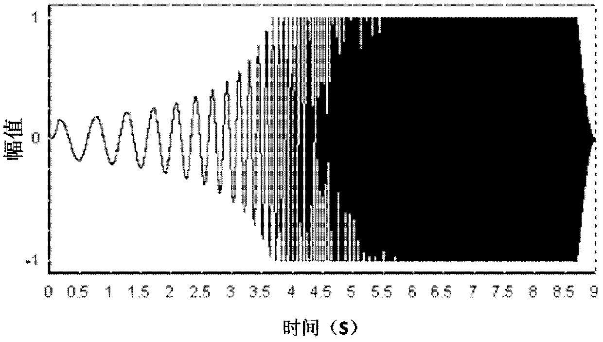
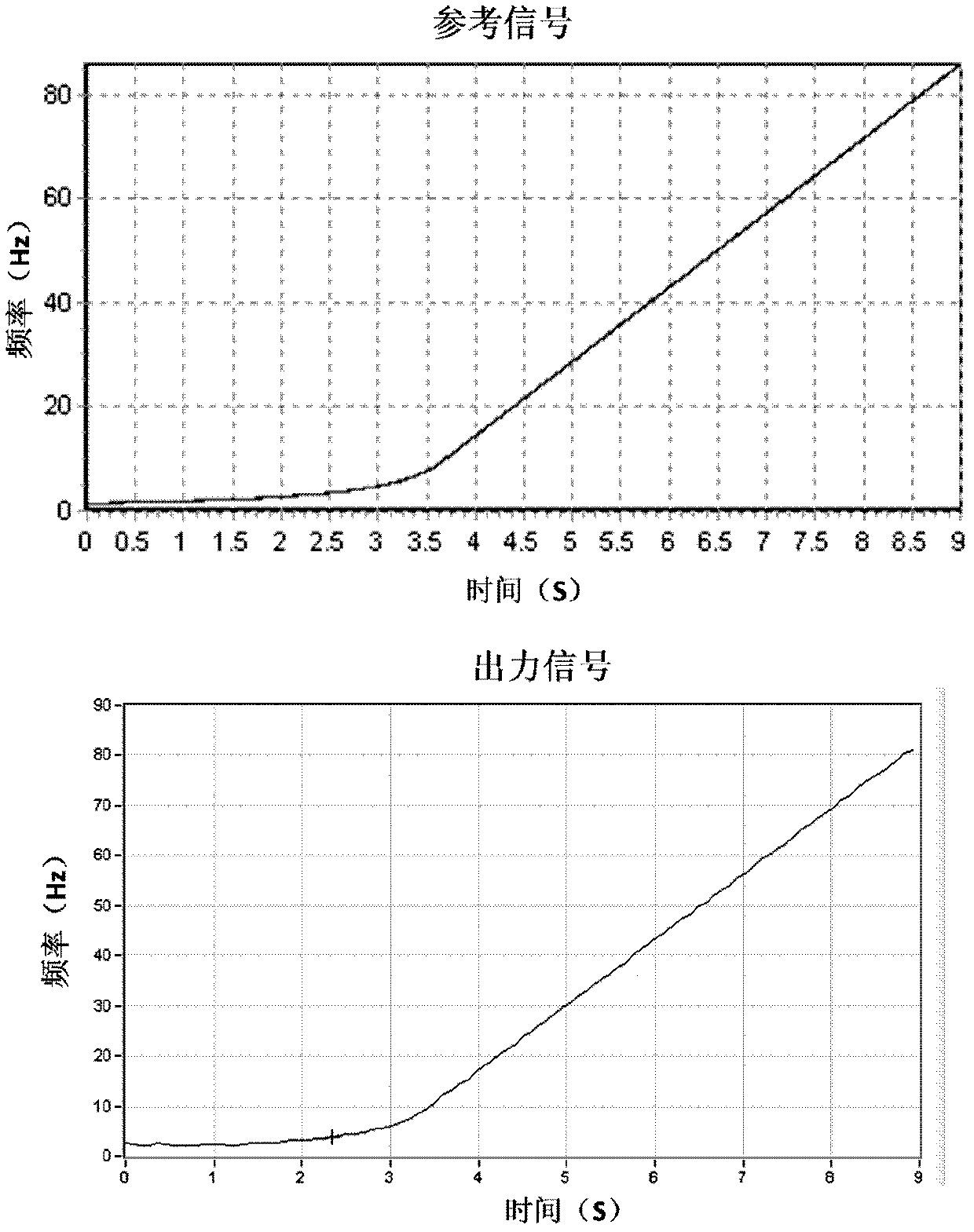
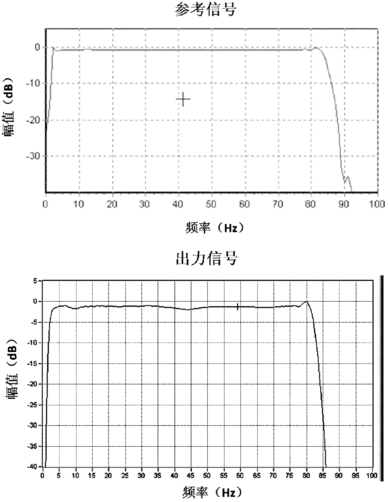
[0076] The main content of the present invention is to design a scanning signal that can be produced by a seismic source to strengthen the low-frequency component by using the actual output maximum output force of each frequency point in the determined frequency domain range for different models of conventional seismic source low-frequency sample points; The signal is actually tested with a seismic source, and the design is corrected according to the test results to obtain the best scanning signal for seismic acquisition; to achieve the best low-frequency exploration performance of each type of conventional seismic source.

[0077] The present invention determines the method for the optimal low-frequency scanning signal of a vibrator, for example, the specific implementation is as follows:

[0078] The vibrator used is AHV-IV362, its technical parameters are shown in Table 1, and the control box is VE464.

[0079] Table 1 AHV-IV362 related technical parameters

[0080]

[...


PUM


Abstract

The invention discloses a method determining a controllable vibration source best low-frequency scanning signal. Equal-frequency scanning signals are adopted, vibration source output force is increased gradually to carry out excitation, the least square method is used for carrying out matching on measured vibration source low-frequency sampling point actual output maximum output force, a controllable vibration source low-frequency output curve is determined according to a fitting heavy punch maximum displacement curve and the focus of a system flow curve, a low-frequency section scanning time length is calculated, the frequency, amplitude and phase of each sampling point of the low-frequency section are calculated, a scanning signal is generated to carry out practical testing on the vibration source, and the best low-frequency scanning signal is obtained until a vibration result does not exceed heavy hammer displacement limitation or the flow limitation. According to the method determining the controllable vibration source best low-frequency scanning signal, the low-frequency components of the controllable vibration source scanning signal are significantly enhanced, the method determining the controllable vibration source best low-frequency scanning signal is suitable for an existing controllable vibration source, can exert the maximum potential of the low frequency of the controllable vibration source, the low frequency signal is small in signal distortion, the output frequency spectrum of the controllable vibration source is smooth and white-noised, and the controllable vibration source can be protected well.

Description

technical field [0001] The invention belongs to the scanning signal design technology of a land vibrator in seismic exploration, and is a method for determining the best low-frequency scanning signal of a vibrator. Background technique [0002] In the oil and gas industry, geophysical exploration techniques are commonly used to find and evaluate underground oil and gas reserves. Earthquakes are artificially excited to generate a seismic wave that travels underground. Usually, at least part of the seismic signal is reflected by an underground seismic reflector (for example, the interface between layers of different acoustic impedance). These reflections are picked up by seismometers placed near the surface, in the water, or in wells of defined depth, while seismic instruments are used at the surface to record the propagation of seismic waves through subsurface formations. Through data processing, analysis and interpretation, study the characteristics of underground geologica...

Claims


Application Information

Patent Timeline
IPC IPC(8): G01V1/28G01V1/30
CPCG01V1/005
Inventor 陶知非刘志刚王井富刘金中关业志曹务祥梁晓峰雷云山王彦娟李扬胜王光德肖明法炜马铁荣徐莉萍
Owner BC P INC CHINA NAT PETROLEUM CORP
Learn More