Three-station insulation earthing switch

An isolated grounding switch, three-station technology, applied in the field of electrical switchgear, can solve the problems of error accumulation in the chute, low transmission precision, low transmission efficiency, etc., to improve the grounding reliability, simple structure and convenient operation. Effect

Inactive Publication Date: 2013-09-25
BEIJING ELECTRIC POWER RES INST HUAYUANELECTRIC POWER TECH
5 Cites 13 Cited by

AI-Extracted Technical Summary

Problems solved by technology

[0006] The three-station isolation-grounding switch in the prior art mostly adopts connecting rod transmission between the operating shaft and the main shaft, the transmission efficiency is low, and the chute of the connecting rod transmission mechanism will have error accumulation during the transmission process, resulting in transmission accuracy. lower
In additi...

Method used

The three-station isolation grounding switch of the present invention adopts gear transmission to realize the grounding operation of the three-station isolation grounding switch, and adopts connecting rod transmission to realize the closing and isolation operations of the three-station isolation grounding switch, which not only drives precision , reduces the error, effectively improves the grounding reliability, and the structure is simple and easy to operate.
[0051] According to one embodiment of the present invention...

Abstract

The invention discloses a three-station insulation earthing switch. The three-station insulation earthing switch comprises a main shaft, an earthing shaft and an insulation shaft, wherein a main shaft limiting crank arm and a driven wheel are connected to the main shaft, the main shaft limiting crank arm is located above the driven wheel, a driving wheel and a sector earthing shaft plate are connected to the earthing shaft, the driving wheel is located above the sector earthing shaft plate, the driving wheel is meshed with the driven shaft, an insulation shaft crank arm and a sector insulation shaft plate are connected to the insulation shaft, the insulation shaft crank arm is located above the sector insulation shaft plate, a connecting rod is connected between the insulation shaft crank arm and the main shaft liming crank arm, one end of the connecting rod is movably connected with the main shaft limiting crank arm, and the other end of the connecting rod is connected with the insulation shaft crank arm in a sliding mode. According to the three-station insulation earthing switch, ground connection of the three-station insulation earthing switch is achieved through gear transmission, switching-on and insulation of the three-station insulation earthing switch are achieved by means of transmission of the connecting rod, therefore, the transmission is accurate, the reliability of ground connection is effectively improved, and the three-station insulation earthing switch is simple in structure and convenient to operate.

Application Domain

Technology Topic

Image

  • Three-station insulation earthing switch
  • Three-station insulation earthing switch
  • Three-station insulation earthing switch

Examples

  • Experimental program(1)

Example Embodiment

[0030] The technical solutions in the embodiments of the present invention will be clearly and completely described below in conjunction with the accompanying drawings in the embodiments of the present invention. Obviously, the described embodiments are only a part of the embodiments of the present invention, rather than all the embodiments. Based on the embodiments of the present invention, all other embodiments obtained by those of ordinary skill in the art without creative work shall fall within the protection scope of the present invention.
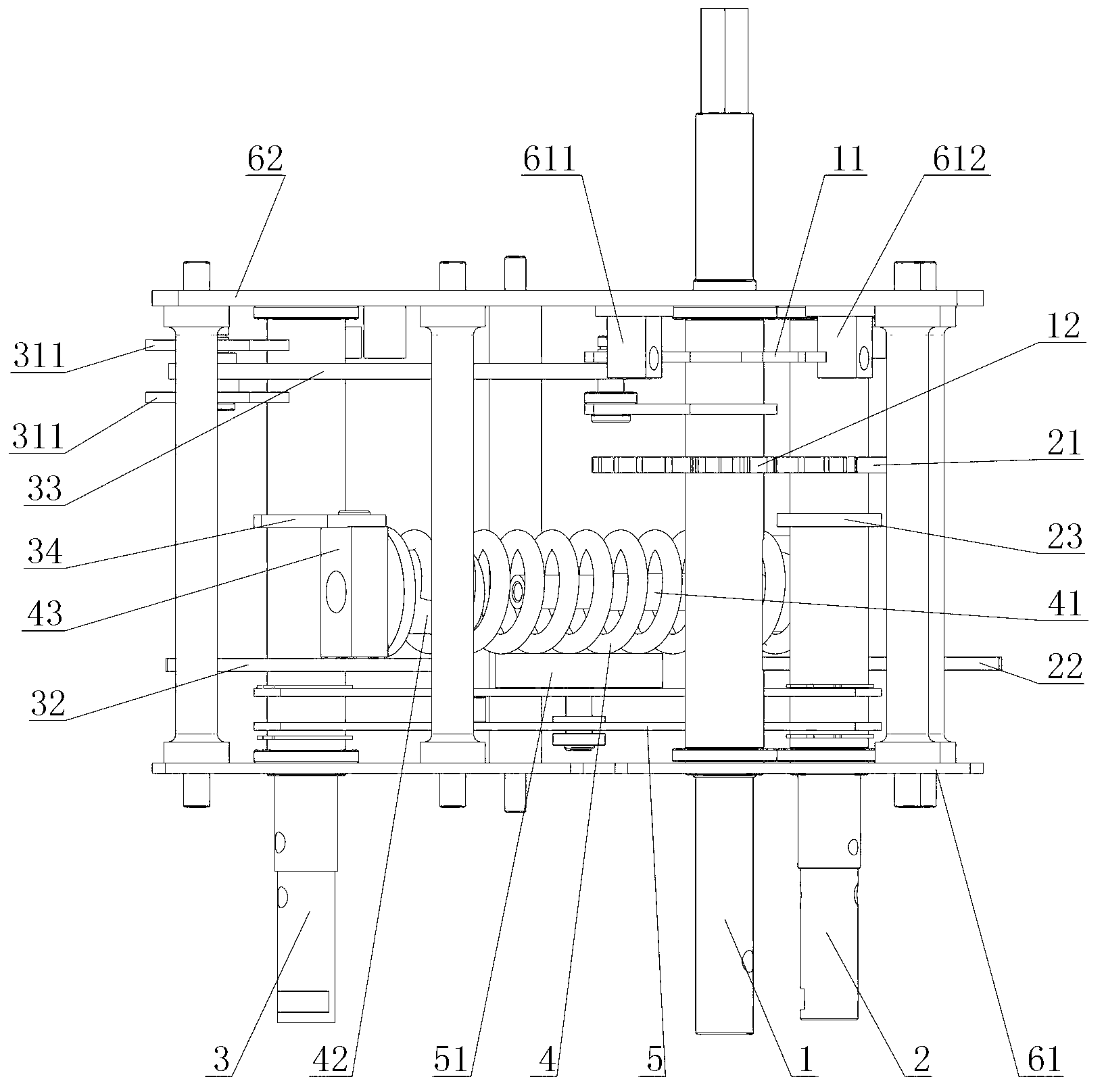
[0031] The position relationship between up, down, left and right described in this article is for figure 2 As shown.
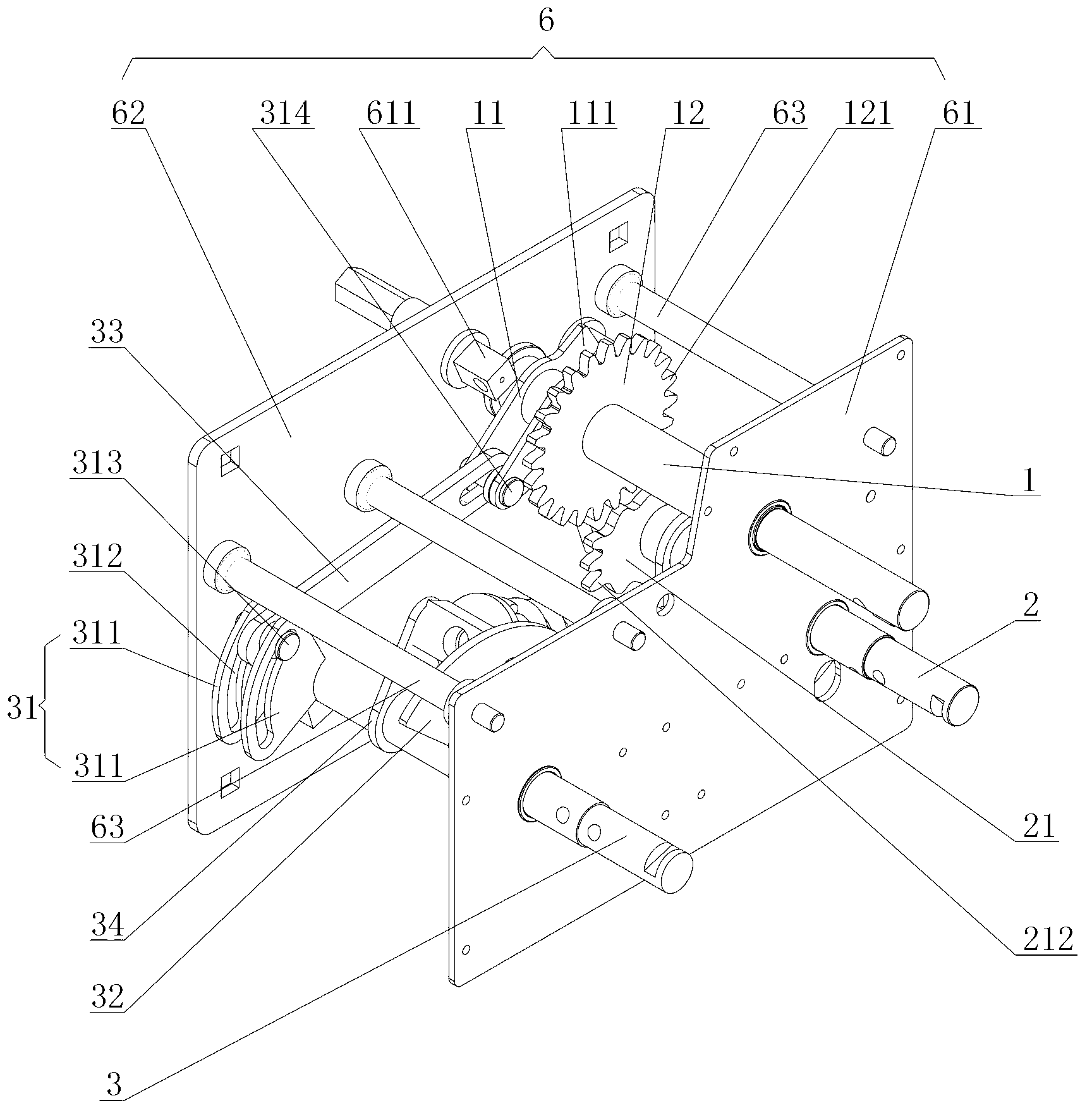
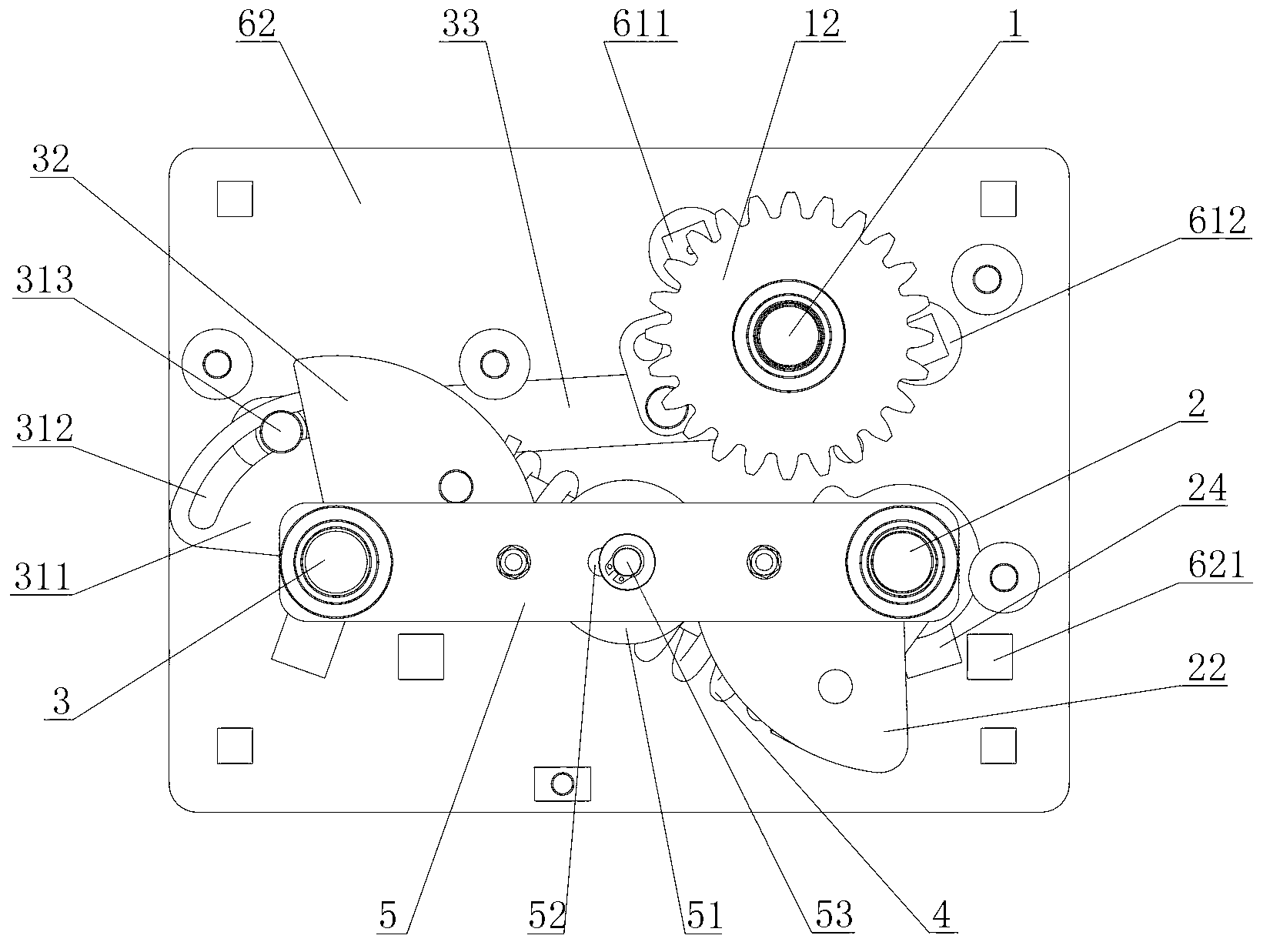
[0032] Such as figure 1 As shown, the present invention provides a three-station isolation grounding switch, which includes a main shaft 1, a grounding shaft 2 and an isolation shaft 3. Wherein: the main shaft 1 is connected with a main shaft limiting arm 11 and a driven wheel 12, the main shaft limiting arm 11 is located above the driven wheel 12; the grounding shaft 2 is connected with a driving wheel 21 and a grounding shaft sector plate 22 , The driving wheel 21 is located above the ground shaft sector plate 22, the driving wheel 21 is engaged with the driven wheel 12; the isolation shaft 3 is connected with an isolation shaft arm 31 and an isolation shaft sector plate 32, so The isolation shaft turning arm 31 is located above the isolation shaft sector plate 32, and a connecting rod 33 is connected between the isolation shaft turning arm 31 and the spindle limit turning arm 11, and one end of the connecting rod 33 is rotatable The ground is connected to the main shaft limiting arm 11, and the other end of the connecting rod 33 is slidably connected to the isolating shaft arm 31.
[0033] Specifically, please refer to figure 2 As shown, the main shaft 1 is fixedly connected with the main shaft limiting arm 11 and the driven wheel 12, that is, the main shaft limiting arm 11 and the driven wheel 12 rotate with the rotation of the main shaft 1. In this embodiment, all outer peripheral edges of the driven wheel 12 are provided with meshing teeth 121, that is, the driven wheel 12 is a full-tooth gear; the main shaft limiting arm 11 is located above the driven wheel 12, and its outer edge The finite protrusion 111 is projected upward.
[0034] The grounding shaft 2 is located on the right side of the main shaft 1, and the driving wheel 21 and the grounding shaft sector plate 22 are fixedly connected to it. That is, the driving wheel 21 and the grounding shaft sector plate 22 rotate with the rotation of the grounding shaft 2. In the present invention, a plurality of meshing teeth 212 are provided on a part of the outer periphery of the driving wheel 21, that is, meshing teeth 212 are provided on a part of the outer periphery of the driving wheel 21, and there is no For meshing teeth, the driving wheel 21 is a special-shaped gear. In this embodiment, three meshing teeth 212 are provided on the driving wheel 21.
[0035] The isolation shaft 3 is located on the left side of the main shaft 1, and the isolation shaft arm 31 and the isolation shaft sector plate 32 are fixedly connected to it, that is, the isolation axis arm 31 and the isolation shaft sector plate 32 rotate with the rotation of the isolation shaft 3 . In the present invention, the isolation shaft turning arm 31 includes two parallel sector plates 311, the sector plates 311 are provided with arc-shaped sliding grooves 312; the isolation shaft turning arm 31 movably connected to the isolation shaft 3 and the main shaft 1 The connecting rod 33 between the main shaft limiting arms 11 is generally in the shape of a long strip plate, one end of which is slidably connected to the arc sliding grooves 312 of the two sector plates 311 through a pin 313, that is, the pin The shaft 313 drives one end of the connecting rod 33 to move in the arc-shaped sliding groove 312 of the sector plate 311; the other end of the connecting rod 33 is rotatably connected to the spindle limit arm 11 through the pin 314, that is, the connecting rod 33 The other end of the shaft and the main shaft limiting arm 11 can rotate with the pin shaft 314 as an axis.
[0036] The operation process of the three-station isolation grounding switch for grounding-isolation-closing is as follows: First, please refer to image 3 As shown, when the three-station isolation grounding switch is in image 3 In the grounding position shown, in this state, it is defined that the main shaft 1 is at the grounding position. By operating the grounding shaft 2, the grounding shaft 2 is rotated clockwise. In the present invention, after the grounding shaft 2 is rotated 30 degrees clockwise, it is connected to the ground The meshing teeth 212 of the driving wheel 21 on the shaft 2 just mesh with the meshing teeth 121 of the driven wheel 12 of the main shaft 1. At this time, continue to rotate the grounding shaft 2. Due to the meshing relationship between the driving wheel 21 and the driven wheel 12, the main shaft 1 will Driven by the grounding shaft 2, rotate to an isolated position, that is Figure 4 The location shown.
[0037] When the three-station isolation grounding switch is in Figure 4 In the isolation position shown, the grounding shaft 2 is operated to rotate the grounding shaft 2 counterclockwise. In the present invention, after the grounding shaft 2 is rotated 30 degrees counterclockwise, the driving wheel 21 connected to the grounding shaft 2 is engaged The teeth 212 just mesh with the meshing teeth 121 of the driven wheel 12 of the main shaft 1. At this time, continue to rotate the grounding shaft 2, and the main shaft 1 will rotate to the aforementioned under the driving of the grounding shaft 2 image 3 The grounding position shown; when the three-station isolation grounding switch is in Figure 4 At the isolation position shown, by operating the isolation shaft 3 to rotate the isolation shaft 3 clockwise, the main shaft 1 will be slidably connected to the isolation shaft arm 31 of the isolation shaft 3, the connecting rod 33, and the isolation shaft arm 31. And the spindle limit arm 11 rotatably connected with the connecting rod 33 is driven to rotate to a closing position, that is, Figure 5 The location shown.
[0038] When the three-station isolation grounding switch is in Figure 5 At the closing position shown, by operating the isolating shaft 3 to make the isolating shaft 3 rotate counterclockwise, the main shaft 1 will be slidably connected to the isolating shaft arm 31 of the isolating shaft 3 and the connecting rod 33 connected to the isolating shaft arm 31 , And the spindle limit arm 11 rotatably connected to the connection 33 rotates to the aforementioned Figure 4 The isolation position shown.
[0039] The three-station isolation grounding switch of the present invention adopts gear transmission to realize the grounding operation of the three-station isolation grounding switch, and adopts connecting rod transmission to realize the closing and isolation operations of the three-station isolation grounding switch, which not only has precise transmission, but also reduces The error is reduced, the grounding reliability is effectively improved, the structure is simple, and the operation is convenient.
[0040] According to an embodiment of the present invention, a spring 4 is connected between the ground shaft 2 and the isolation shaft 3. Specifically, the ground shaft spring positioning arm 23 is fixedly connected to the ground shaft 2, that is, the ground shaft spring positioning arm 23 rotates with the rotation of the ground shaft 2, and the ground shaft spring positioning arm 23 is located at Between the driving wheel 21 and the ground shaft sector plate 22, one end of the spring 4 is penetrated with a spring positioning shaft 41, and the spring positioning shaft 41 is rotatably connected by a pin shaft (not shown in the figure) Between the grounding shaft spring positioning arm 23 and the grounding shaft sector plate 22, the spring positioning shaft 41 can rotate between the grounding shaft spring positioning arm 23 and the grounding shaft sector plate 22 by using a pin as an axis.
[0041] Further, the isolation shaft 3 is fixedly connected with an isolation shaft spring positioning arm 34, that is, the isolation shaft spring positioning arm 34 rotates with the rotation of the isolation shaft 3, and the isolation shaft spring positioning arm 34 is located at Between the isolation shaft arm 31 and the isolation shaft sector plate 32, the other end of the spring 4 is provided with a spring compression sleeve 42 which is rotatably connected to the said spring via a pin 43. The isolating shaft spring positioning arm 34 and the isolating shaft fan-shaped plate 32, the spring compression sleeve 42 can rotate between the isolating shaft spring positioning arm 34 and the isolating shaft fan plate 32 using the pin shaft 43 as an axis.
[0042] The spring 4 of the present invention can serve the purpose of assisting the rotation of the ground shaft 2 and the isolation shaft 3. When the three-station isolation grounding switch is switched from the grounding position to the isolating position, after the grounding shaft 2 has rotated 30 degrees clockwise, the meshing teeth 212 of the driving wheel 21 on the grounding shaft 2 rotates to the driven wheel 12 of the main shaft 1. During this process, the spring 4 is in the stage of compressing and storing energy. Due to the meshing relationship between the driving wheel 21 and the driven wheel 12, when the grounding shaft 2 rotates to the position where the spring 4 releases energy, the spring 4 The stored elastic potential energy will drive the grounding shaft 2 to continue to rotate clockwise, so that the main shaft 1 is switched from the grounding position to the isolation position under the driving of the grounding shaft 2. At this time, the driving wheel 21 and the driven wheel 12 are disengaged without disturbing the isolation The operation of axis 3 to spindle 1. Conversely, when the three-station isolation grounding switch is switched from the isolation position to the grounding position, after the grounding shaft 2 has turned 30 degrees counterclockwise, the meshing teeth 212 of the driving wheel 21 on the grounding shaft 2 rotates to the slave The meshing teeth 121 of the driving wheel 12 are engaged. During this process, the spring 4 is in the stage of compressing and storing energy. Due to the meshing relationship between the driving wheel 21 and the driven wheel 12, when the grounding shaft 2 rotates to the position where the spring 4 releases energy, The elastic potential energy stored by the spring 4 will drive the grounding shaft 2 to continue to rotate counterclockwise, so that the main shaft 1 is switched from the isolation position to the grounding position under the drive of the grounding shaft 2. At this time, the driving wheel 21 is disengaged from the driven wheel 12. Interference isolation shaft 3 to the operation of main shaft 1.
[0043] When the three-station isolation and grounding switch is switched from the isolation position to the closing position, the spring 4 is in the stage of compression and energy storage when the isolation shaft 3 rotates 30 degrees clockwise. When the spring 4 crosses its compression critical point , Will drive the spindle 1 to rotate clockwise by releasing the elastic potential energy, so that the spindle 1 is switched from the isolation position to the closing position; on the contrary, when the three-station isolation grounding switch is switched from the closing position to the isolation position, the isolation shaft 3 In the process of turning 30 degrees counterclockwise, the spring 4 is in the stage of compression and energy storage. When the spring 4 crosses its compression critical point, it will release the elastic potential energy to drive the spindle 1 to rotate counterclockwise to switch the spindle 1 from the closing position Go to the isolation location.
[0044] According to an embodiment of the present invention, the lower end of the grounding shaft 2 is provided with a connecting plate 5, the other end of the connecting plate 5 is sleeved on the isolating shaft 3, and the middle of the connecting plate 5 is movably An interlocking wheel 51 is connected, and the interlocking wheel 51 movably contacts the ground shaft sector plate 22 and the isolation shaft sector plate 32 respectively.
[0045] Specifically, the two ends of the connecting plate 5 are respectively provided with perforations (not shown in the figure), the lower end of the isolation shaft 3 and the lower end of the grounding shaft 2 are respectively penetrated through the two perforations of the connecting plate 5, and the middle of the connecting plate 5 A through groove 52 is provided; the interlocking wheel 51 is generally in the shape of a flat cylinder, and its lower end surface is slidably connected to the connecting plate 5 through a pin 53 through the through groove 52. The interlocking wheel 51 is located on the same horizontal plane as the ground shaft sector plate 22 of the ground shaft 2 and the isolation shaft sector plate 32 of the isolation shaft 3.
[0046] The interlocking wheel 51 of the present invention can achieve the purpose of safely locking the three-station isolation grounding switch in the grounding state and the closing state. When the three-station isolation grounding switch is in the grounding position and the grounding shaft 2 rotates clockwise, the grounding shaft sector plate 22 on it is in close contact with the interlocking wheel 51, pushing the interlocking wheel 51 to the isolation shaft of the isolation shaft 3. The side of the sector plate 32 prevents the isolating shaft 3 from rotating clockwise and drives the main shaft 1 to the closing position, so as to achieve safe lock in the grounding state; when the three-station isolating and grounding switch is in the closing position, the isolating shaft 3 is When rotating clockwise, the isolation shaft sector plate 32 on it is in close contact with the interlocking wheel 51, pushing the interlocking wheel 51 to the side of the grounding shaft sector plate 22 of the grounding shaft 2, preventing the grounding shaft 2 from rotating counterclockwise and driving the main shaft 1 Turn to the grounding position to achieve safety lock in the closed state.
[0047] According to an embodiment of the present invention, the three-station isolation grounding switch further includes a support plate 6 having a front support plate 61 and a rear support plate 62, the front support plate 61 and the rear support plate 62 are parallel to each other, and two ends of the main shaft 1, the ground shaft 2 and the isolation shaft 3 are rotatably connected to the front support plate 61 and the rear support plate 62, respectively.
[0048] Specifically, a plurality of fixed rods 63 are connected between the front support plate 61 and the rear support plate 62, and the two ends of the main shaft 1, the grounding shaft 2 and the isolation shaft 3 are respectively rotatably connected to the front support plate 61 and the rear support plate 61 through bearings. On the plate 62, the front support plate 61 and the rear support plate 62 are used to fix the relative positions of the main shaft 1, the ground shaft 2 and the isolation shaft 3.
[0049] Further, the front support plate 61 is provided with a closing limit stop pin 611 and a ground limit stop pin 612. According to the rotational movement of the main shaft 1, the main shaft limit arm 11 is respectively connected to the closing The limit stop pin 611 and the ground limit stop pin 612 contact or separate. The closing limit stop pin 611 and the ground limit stop pin 612 are used to limit the rotation angle of the main shaft 1 so as to prevent the main shaft 1 from continuing to rotate when the main shaft 1 rotates to the required closing position and the grounding position.
[0050] When the main shaft 1 rotates from the isolation position to the closing position, the main shaft limit arm 11 connected to the main shaft 1 will be clamped to the closing limit stop pin 611 through its limit protrusion 111, and the main shaft 1 is fixed. in Figure 5 In the closing position shown, the closing limit stop pin 611 is used to prevent the main shaft 1 from continuing to rotate under the driving of the isolating shaft 3. When the spindle 1 rotates from the isolated position to the grounded position, the spindle limit arm 11 connected to the spindle 1 will be clamped to the ground limit stop pin 612 through its limit protrusion 111, and the spindle 1 will be fixed at image 3 In the grounding position shown, the grounding limit stop pin 612 is used to prevent the main shaft 1 from continuing to rotate under the driving of the grounding shaft 2.
[0051] According to an embodiment of the present invention, a limit stop pin 621 is protrudingly provided at a position on the rear support plate 62 close to the grounding shaft 2, and a grounding shaft limiting arm 24 is fixedly connected to the grounding shaft 2. Figure 4 The isolation position shown switches to image 3 When the grounding position is shown, the grounding shaft limiting arm 24 will be stuck at the limiting stop pin 621 to prevent the grounding shaft 2 from continuing to rotate and realize the limiting operation on the grounding shaft 2.
[0052] The above are only a few embodiments of the present invention, and those skilled in the art can make various changes or modifications to the embodiments of the present invention based on the content disclosed in the application documents without departing from the spirit and scope of the present invention.

PUM

no PUM

Description & Claims & Application Information

We can also present the details of the Description, Claims and Application information to help users get a comprehensive understanding of the technical details of the patent, such as background art, summary of invention, brief description of drawings, description of embodiments, and other original content. On the other hand, users can also determine the specific scope of protection of the technology through the list of claims; as well as understand the changes in the life cycle of the technology with the presentation of the patent timeline. Login to view more.

Similar technology patents

Classification and recommendation of technical efficacy words

  • Transmission precision
  • Reduce mistakes

Terminal positioning track fitting method based on Bezier curve

ActiveCN102998684AReduce mistakesSatellite radio beaconingSatellite navigationFitting methods
Owner:XIAMEN YAXON NETWORKS CO LTD

Multifunctional road soil roadbed freezing and thawing circulating test device

ActiveCN101923085ASolving Elasticity ProblemsReduce mistakesRoadwaysEarth material testingTest measurementFrost
Owner:CCCC SECOND HIGHWAY CONSULTANTS CO LTD
Why Eureka
Try Eureka