Automatic feeding equipment capable of precisely conveying ceramic columns

An automatic feeding and ceramic column technology, which is applied in metal processing equipment, metal processing, manufacturing tools, etc., can solve the problems of unstable transmission process, unstable material supply, and low transmission accuracy of ceramic columns, so as to improve the efficiency of material receiving and transmission , reduce production costs, and achieve a high degree of intelligence

Pending Publication Date: 2018-05-15
HUNAN SUPER INFORMATION
View PDF0 Cites 1 Cited by
  • Summary
  • Abstract
  • Description
  • Claims
  • Application Information

AI Technical Summary

Problems solved by technology

[0005] In the existing automatic sensor assembly equipment, the assembly process of the ceramic column is relatively simple. First, the ceramic column is transferred to the corresponding station through the automatic feeding equipment, and then the material is directly picked up by the manipulator, and then sent to the corresponding station for assembly. That is, the existing automatic feeding equipment for conveying ceramic columns has the following defects: 1) Since sensors with different parameters require different specifications of ceramic columns, the same set of automatic feeding equipment can only deliver a single specification of ceramic columns , When transferring ceramic columns of different specifications, it is necessary to repl

Method used


Image

  • Automatic feeding equipment capable of precisely conveying ceramic columns
  • Automatic feeding equipment capable of precisely conveying ceramic columns
  • Automatic feeding equipment capable of precisely conveying ceramic columns

Examples


Example Embodiment

[0037] The present invention will be further described in detail below in conjunction with the accompanying drawings and specific embodiments.

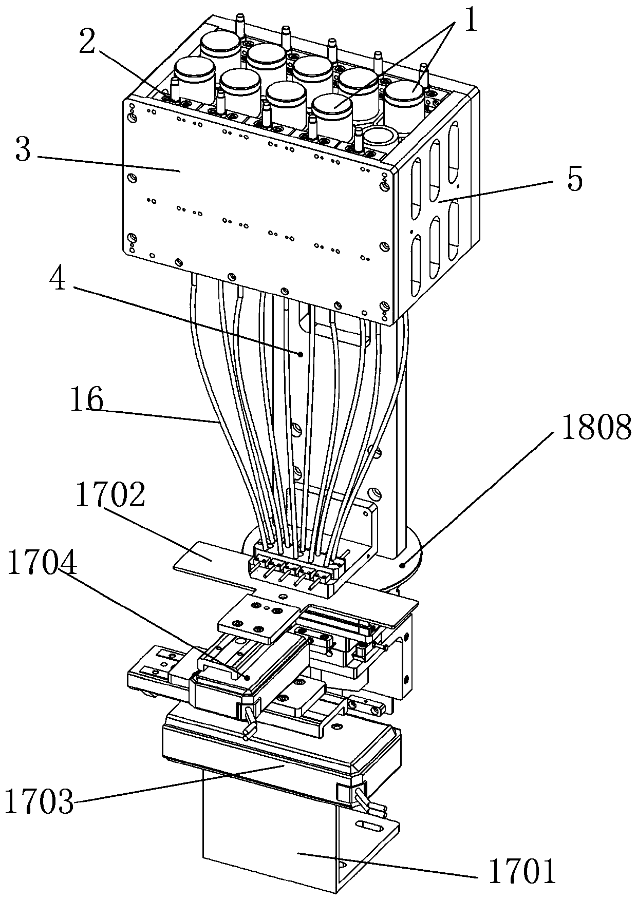
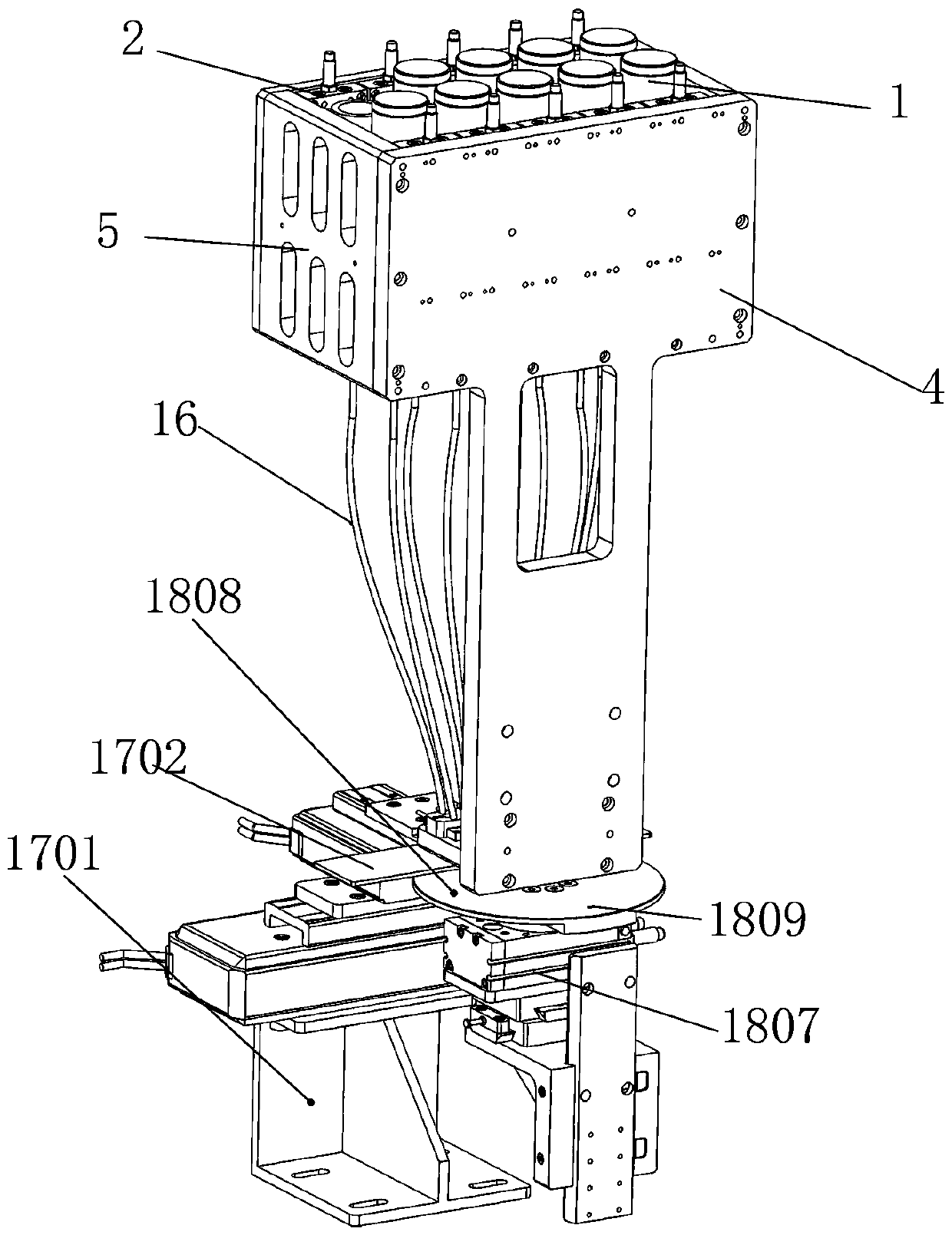
[0038] In this embodiment, refer to Figure 1-Figure 10 , the automatic feeding equipment that can accurately transfer the ceramic column includes a feeding mechanism, a material receiving mechanism 17 and a feeding mechanism 18, such as figure 1 and figure 2 As shown, the feeding mechanism is located above the material receiving mechanism 17, and the feeding mechanism 18 is located at the rear of the material receiving mechanism 17. The feeding mechanism is used for storing and supplying porcelain columns, and the material receiving mechanism 17 is used for accepting the porcelain columns supplied by the feeding mechanism. column, and accurately delivered to the feeding mechanism 18, the feeding mechanism 18 is used to deliver the ceramic column to the automatic assembly process.

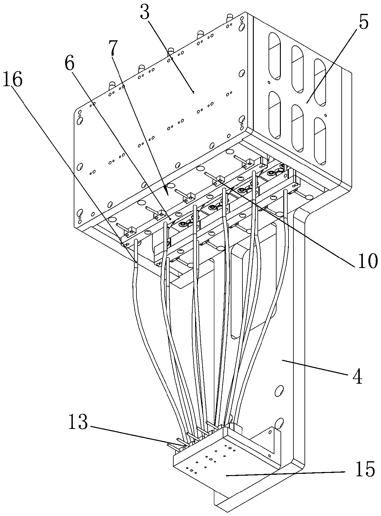
[0039] like Figure 3-8 As shown, the feeding me...


PUM


Abstract

The invention relates to automatic feeding equipment capable of precisely conveying ceramic columns in the field of automatic equipment. The equipment comprises a supply mechanism, a receiving mechanism and a feeding mechanism; the supply mechanism comprises a bin module, a lifting cylinder and a bin protecting plate; the bin protecting plate is encircled to form a square cavity for accommodatingautomatic supply modules; more than four sets of automatic supply modules with the same structures are arranged in the square cavity; the receiving mechanism comprises a receiving bracket, and a receiving plate arranged on the receiving bracket; a plane movable platform is arranged between the receiving bracket and the receiving plate; the feeding mechanism comprises a feeding bracket, and a rotary feeding module arranged on the feeding bracket; the rotary feeding module comprises a rotating cylinder and a feeding disc; the supply mechanism is used for storing and supplying the ceramic columns; the receiving mechanism is used for bearing the ceramic columns supplied by the supply mechanism and precisely conveying to the feeding mechanism; the feeding mechanism is used for conveying the ceramic columns to an automatic assembly procedure; and all the mechanisms are corresponding to each other, and are connected as a whole to finish precise feeding.

Description

technical field [0001] The invention relates to the field of automation equipment, in particular to an automatic feeding system, in particular to an automatic feeding device capable of accurately conveying ceramic columns. Background technique [0002] A sensor is a detection device that can sense the measured information and convert the sensed information into electrical signals or other required forms of information output according to certain rules to meet the requirements of information transmission, processing, storage, and display. , recording and control requirements. [0003] Ceramic sensor refers to a sensing device that uses ceramic materials to sense measurement signals and convert output. Ceramic is a recognized material with high elasticity, corrosion resistance, wear resistance, shock and vibration resistance, and has excellent thermal properties. Stability, and high-performance, low-price ceramic sensors will be the development direction of pressure sensors. ...

Claims


Application Information

Patent Timeline
IPC IPC(8): B23P19/00
CPCB23P19/001
Inventor 胡炎良
Owner HUNAN SUPER INFORMATION
Why Eureka
Try Eureka