Supercharge Your Innovation With Domain-Expert AI Agents!

Process and apparatus for conversion of silicon tetrachloride to trichlorosilane

A technology of silicon tetrachloride and chlorosilane, applied in silicon halide compounds, chemical instruments and methods, silicon hydride, etc., can solve the problem of low yield of trichlorosilane

Inactive Publication Date: 2013-09-25
WACKER CHEM GMBH
View PDF15 Cites 3 Cited by
  • Summary
  • Abstract
  • Description
  • Claims
  • Application Information

AI Technical Summary

Problems solved by technology

Thus the actually increased trichlorosilane yield was much lower than first expected

Method used


Image

  • Process and apparatus for conversion of silicon tetrachloride to trichlorosilane
  • Process and apparatus for conversion of silicon tetrachloride to trichlorosilane
  • Process and apparatus for conversion of silicon tetrachloride to trichlorosilane

Examples


Embodiment 3a

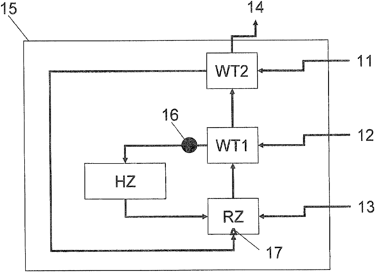
[0130] In this example, using the figure 1 of the reactor.

[0131] For the heat exchanger unit WT1, isobaric graphite was used.

[0132] According to the invention, the process was carried out similarly to Comparative Example 1, except that hydrogen and silicon tetrachloride were heated separately.

[0133] The hydrogen is raised to a temperature of 500°C in the second heat exchanger and introduced directly into the reaction zone before the hydrogen is mixed with the silicon tetrachloride in the reaction zone, and the tetrachloride is mixed with the silicon tetrachloride in the first heat exchanger. The silicon carbide is preheated to about 920°C and then heated to 1350°C by means of an electric heating element. The average temperature in the reaction zone is about 1000°C.

[0134] The relative selectivity of the reactor was increased to 145%.

[0135] It was also found that after shutting down the reactor, the heater was still intact. Any effect of methanation could not...

Embodiment 3b

[0137] Example 3b was carried out similarly to Example 3a, except that the pressure difference between the reactant side and the product side of the heat exchanger unit WT1 was in the range of 10 mbar to 1000 mbar by incorporating various throttling valves internal changes.

[0138] The optimum obtained has been found at a pressure difference between 50 mbar and 200 mbar while using a minimum graphite wall thickness in the range 4-30 mm (between reactant and product side of heat exchanger unit WT1). good result. However, optimum values ​​are obtained with a minimum wall thickness between 10mm and 20mm.

[0139] The inventors have realized that the use of isobaric graphite for the heat exchanger unit WT1 in combination with a defined pressure difference seems to be optimal.

[0140] It appears that the low porosity of the material allows the formation of a diffuse volume flow to protect the graphite, however establishing a volume flow at a sufficiently low level does not reduce...

Embodiment 4

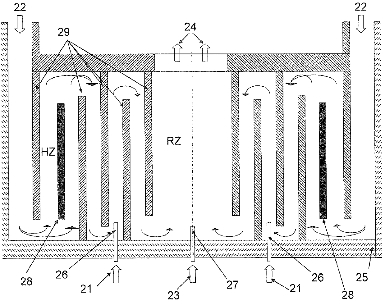
[0143] In addition to Example 3b, dichlorosilane was injected as a third reactant stream 13 in a molar ratio of 3% dichlorosilane to 97% silicon tetrachloride into an additional central nozzle installed at the bottom of the reaction zone. figure 1 A corresponding device with an additional central nozzle is schematically shown in .

[0144] The injected dichlorosilane stream has a temperature between 250°C and 350°C.

[0145] A temperature calibration to preheat the silicon tetrachloride stream in the heating zone is not necessary.

[0146] Use the center nozzle for the inflow of dichlorosilane.

[0147] The central nozzle for introducing dichlorosilane has a diameter of 15 mm.

[0148] This relative selectivity was further improved to 165% relative to structural problems without any apparent adverse effects.


PUM


Abstract

A process for hydrogenating chlorosilanes in a reactor, wherein at least two reactant gas streams are introduced separately from one another into a reaction zone, wherein the first reactant gas stream comprising silicon tetrachloride is conducted via a first heat exchanger unit in which it is heated and is then conducted through a heating unit which heats it to a first temperature before the first reactant gas stream reaches the reaction zone, and wherein the second reactant gas stream comprising hydrogen is heated by a second heat exchanger unit to a second temperature, wherein the first temperature is greater than the second temperature, and then introduced into the reaction zone, such that the mixing temperature of the two reactant gas streams in the reaction zone is between 850 DEG C and 1300 DEG C, and said reactant gas streams react to give product gases comprising trichlorosilane and hydrogen chloride, wherein the product gases obtained in the reaction are conducted through said at least two heat exchanger units and preheat the reactant gas streams of the reaction by the countercurrent principle, wherein the flow passes first through the first heat exchanger unit and then through the second heat exchanger unit. A reactor for hydrogenating chlorosilanes, comprising two gas inlet devices through which reactant gases can be introduced separately from one another into the reactor, and at least one gas outlet device through which a product gas stream can be conducted, at least two heat exchanger units which are connected to one another and which are suitable for heating reactant gases separately from one another by means of the product gases conducted through the heat exchanger units, and a heating zone which is arranged between a first heat exchanger unit and a reaction zone and in which there is at least one heating element.

Description

technical field [0001] The invention provides a method and device for converting silicon tetrachloride into trichlorosilane. Background technique [0002] Trichlorosilane is used to produce polysilicon. [0003] Trichlorosilane is usually prepared from metallurgical silicon and hydrogen chloride in a fluidized bed process. In order to obtain trichlorosilane of high purity, distillation is usually followed. This also provides silicon tetrachloride as a by-product. [0004] Most of the silicon tetrachloride is obtained during the deposition of polysilicon. For example, polysilicon is obtained by means of the Siemens process (open-hearth process, Siemens process). This involves depositing silicon on thin heated rods in a reactor. The process gas used as the silicon-containing component is a halosilane, such as trichlorosilane, in the presence of hydrogen. The conversion of trichlorosilane to deposited silicon (disproportionation reaction) produces large amounts of silicon...

Claims


Application Information

Patent Timeline
Patent Type & Authority Applications(China)
IPC IPC(8): C01B33/107
CPCC01B33/1071Y02P20/129C01B33/04C01B33/107B01J12/00
Inventor 罗伯特·林诺埃米·鲍诺什乌韦·佩特佐尔德
Owner WACKER CHEM GMBH
Features
  • R&D
  • Intellectual Property
  • Life Sciences
  • Materials
  • Tech Scout
  • Unparalleled Data Quality
  • Higher Quality Content
  • 60% Fewer Hallucinations
Learn More