Fluid handling system having dedicated egr turbo-generator

A fluid treatment and turbine technology, applied in fuel heat treatment devices, charging systems, combustion air/combustion-air treatment, etc., can solve problems such as hindering the reduction of NOx and increasing the combustion temperature in the cylinder

Inactive Publication Date: 2013-09-25
CATERPILLAR INC
View PDF8 Cites 2 Cited by
  • Summary
  • Abstract
  • Description
  • Claims
  • Application Information

AI Technical Summary

Problems solved by technology

That is, the exhaust gas that is recirculated back to the engine can contain a large amount of energy in the form of waste heat, which increases the in-cylinder combustion temperature and hinders the desired reduction of NOx

Method used


Image

  • Fluid handling system having dedicated egr turbo-generator
  • Fluid handling system having dedicated egr turbo-generator

Examples


Embodiment Construction

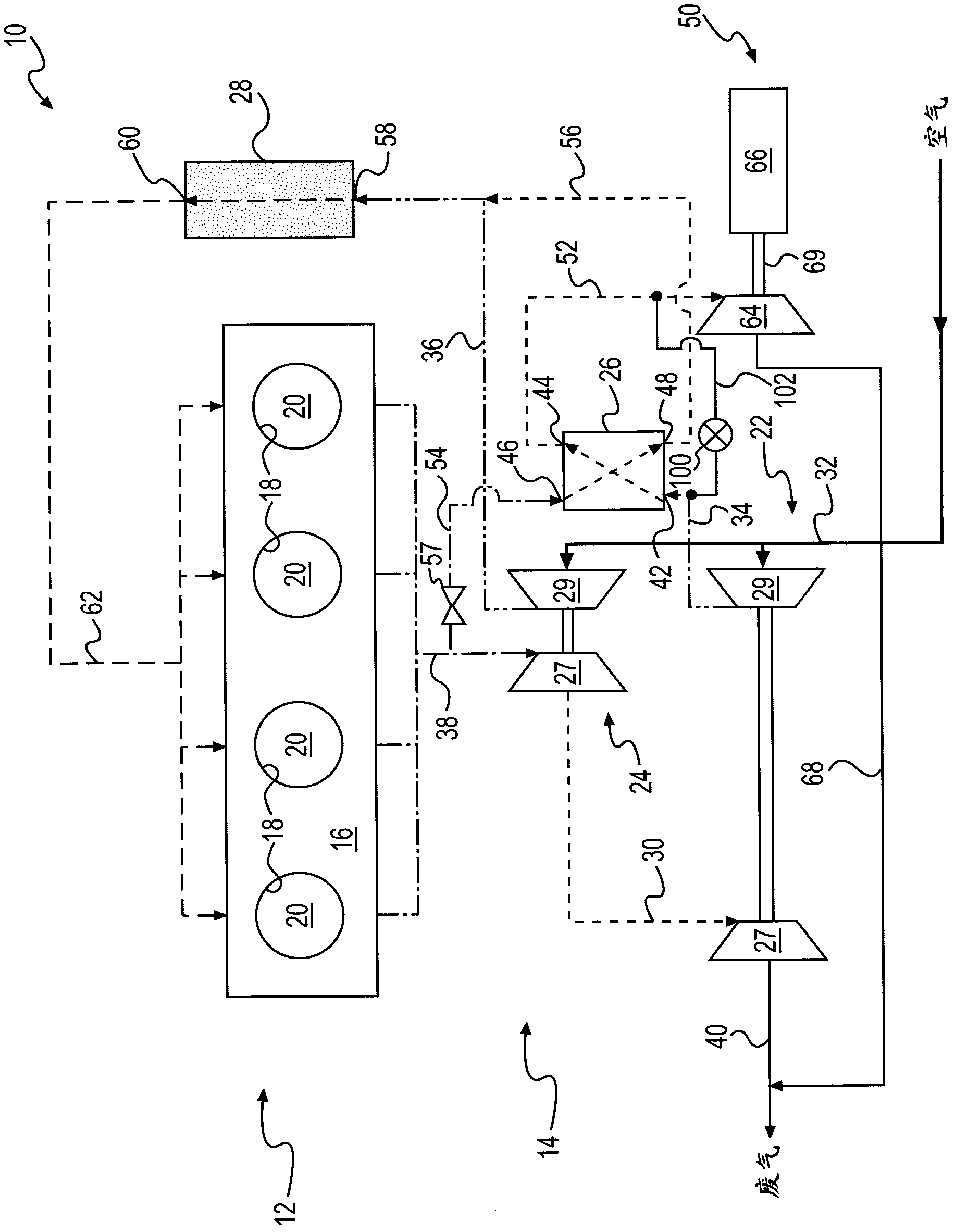
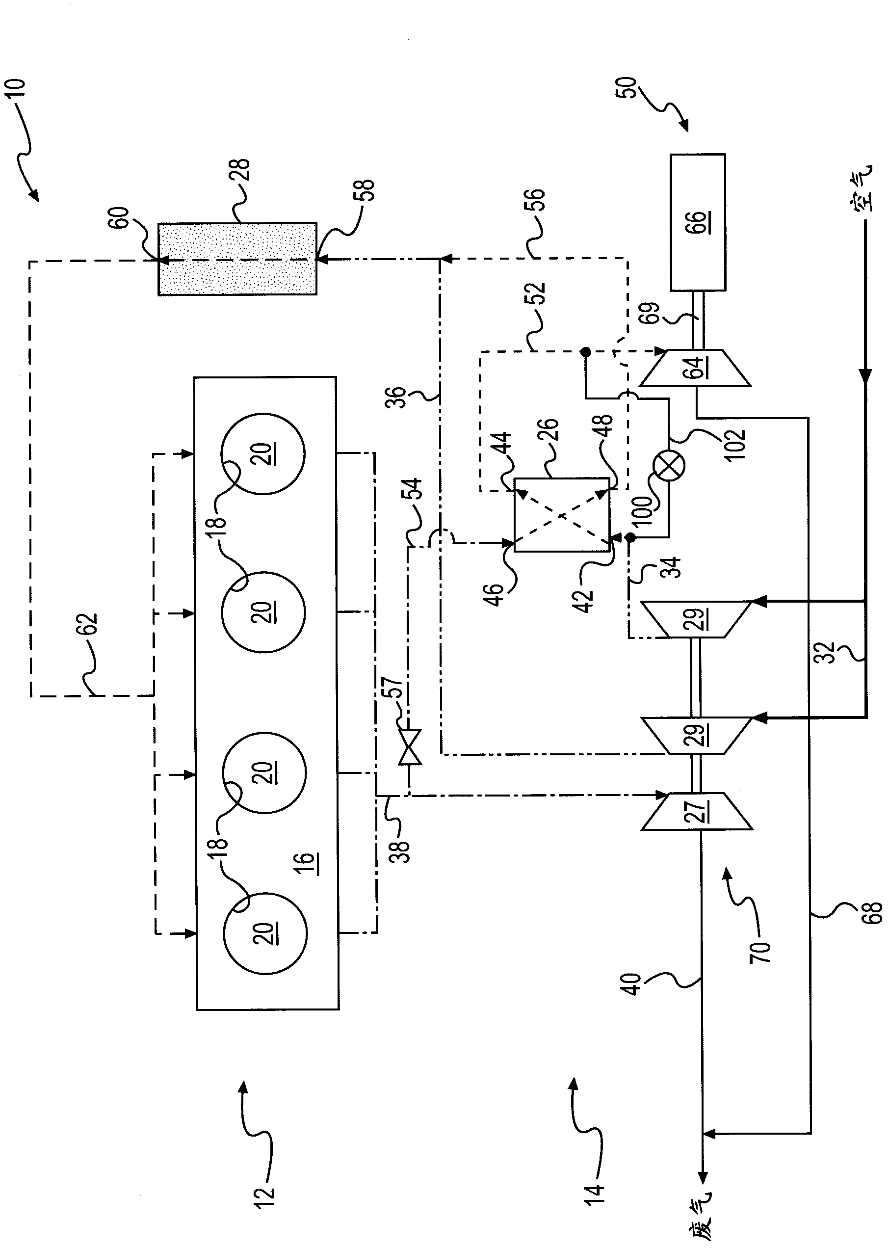
[0010] figure 1 Power system 10 is shown having power source 12 and fluid handling system 14 . For purposes of this disclosure, power source 12 is described and depicted as a four-stroke diesel engine. Those of ordinary skill in the art will recognize, however, that power source 12 may be any other type of combustion engine, such as a gasoline or gaseous fuel powered engine. Power source 12 may include an engine block 16 at least partially defining a plurality of cylinders 18 . A piston (not shown) may be slidably disposed within each cylinder 18 for reciprocating movement between a top dead center position and a bottom dead center position, and one or more cylinder heads (not shown) may be connected to the engine cylinders. body 16 to close the end of each cylinder 18. Each cylinder 18 , piston and head may together define a combustion chamber 20 . In the illustrated embodiment, power source 12 includes four such combustion chambers 20 . However, it is contemplated that ...


PUM


Abstract

A fluid handling system (14) for a use with an engine (12) is provided. The fluid-handling system may have a first turbine (27) connected to receive a portion of an exhaust flow from the engine, a first compressor (29) driven by the first turbine to pressurize an airflow, and a heat exchanger (26) configured to receive a remaining portion of the exhaust flow from the engine and the airflow from the first compressor. The fluid-handling system may also have a second turbine (64) connected to receive the airflow from the heat exchanger, and a generator (66) driven by the second turbine to generate power.

Description

technical field [0001] The present invention relates to a fluid treatment system, and more particularly to a fluid treatment system with a dedicated exhaust gas recirculation (EGR) turbine generator. Background technique [0002] Internal combustion engines, such as diesel engines, gasoline engines, and gaseous fuel powered engines, emit complex mixtures of air pollutants as by-products of the combustion process. These air pollutants include gaseous compounds including, among others, oxides of nitrogen (NOx). Due to increasing environmental concerns, exhaust emission standards have become more stringent, and the amount of NOx emitted from an engine to the atmosphere may be regulated depending on the type of engine, the size of the engine, and / or the rating of the engine. [0003] One method utilized by engine manufacturers to comply with engine emissions regulations is the use of exhaust gas regeneration (EGR). The EGR system recirculates exhaust gases to mix with the comb...

Claims


Application Information

Patent Timeline
IPC IPC(8): F02M25/07F01D15/10F02B39/00
CPCF01N5/02F02B29/0425F02B29/0437F02B37/004F02B37/18F02D29/06F02M31/042F02M31/08F02M26/08F02M26/27F02M26/00Y02T10/12
Inventor S·B·菲维兰德
Owner CATERPILLAR INC
Why Eureka
Try Eureka