Motor rotor, molded motor, air conditioner, and method for producing molded motor

A manufacturing method and motor technology, which is applied in the field of air conditioners, molded motor manufacturing, and molded motors. It can solve the problems of rotor installation and inability to cope with specification changes, and achieve the effect of easy specification changes.

Inactive Publication Date: 2013-09-25
MITSUBISHI ELECTRIC CORP
View PDF7 Cites 18 Cited by
  • Summary
  • Abstract
  • Description
  • Claims
  • Application Information

AI Technical Summary

Problems solved by technology

Therefore, there is a problem that, for example, in the case of a long shaft, the rotor cannot be easily mounted on the shaft, and it may not be possible to cope with specification changes

Method used


Image

  • Motor rotor, molded motor, air conditioner, and method for producing molded motor
  • Motor rotor, molded motor, air conditioner, and method for producing molded motor
  • Motor rotor, molded motor, air conditioner, and method for producing molded motor

Examples


Embodiment approach

[0090] (summary)

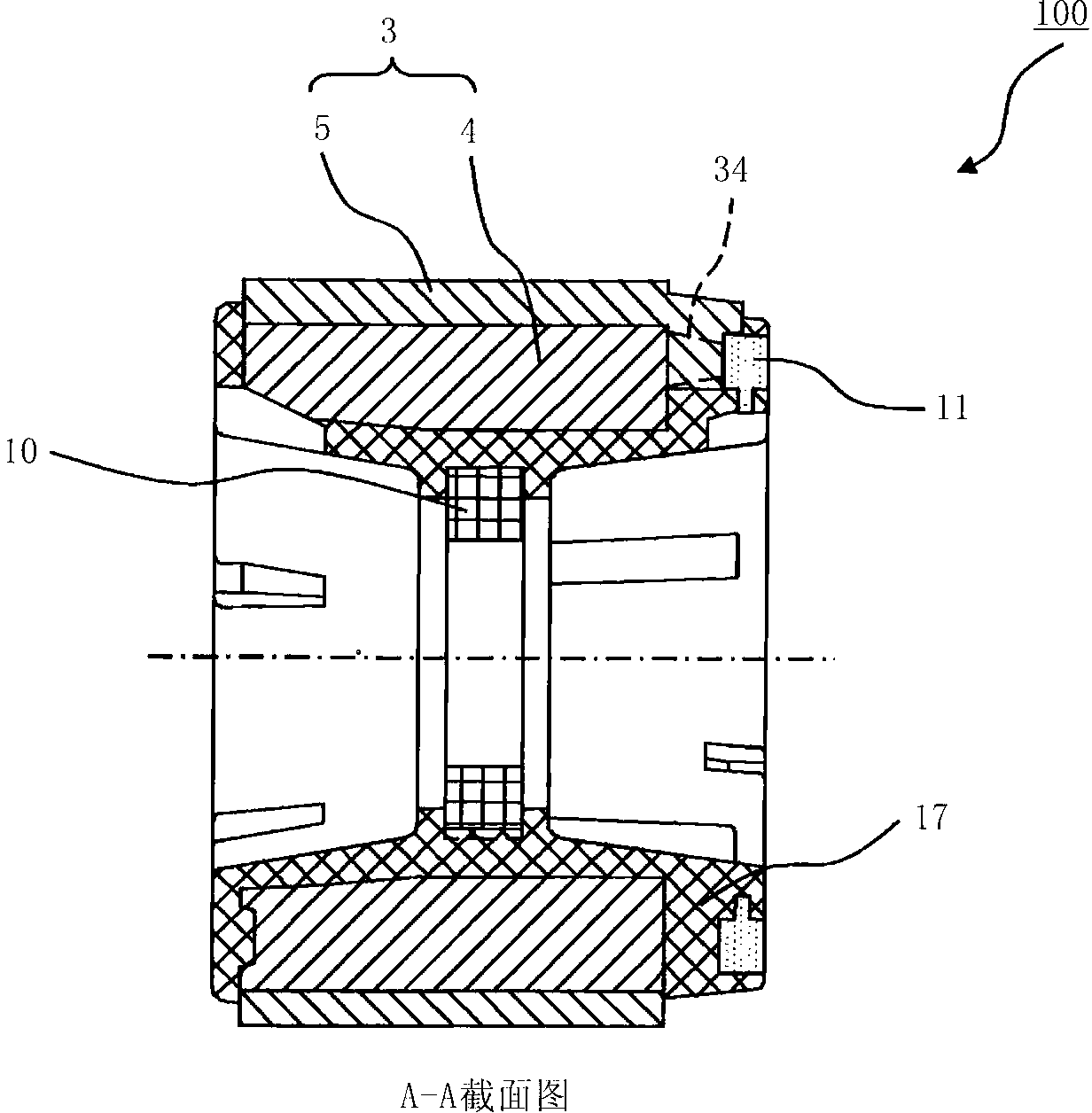
[0091] The rotor of the electric motor according to this embodiment is characterized in that the length (or diameter) of the shaft and the position of the rotor on the shaft can be arbitrarily selected. For example, the rotor of a motor with a load (fan, etc.) attached to only one end of the shaft, since the shaft is short and the position of the rotor on the shaft is determined, the rotor magnet, the magnet for position detection, and the shaft can be integrally molded with resin .

[0092] However, when the shaft is long, when the rotor magnet, the position detection magnet, and the shaft are integrally molded with resin, the length of the shaft is limited by the amount of mold opening during resin molding and cannot be of any length.

[0093] Therefore, different molds are required in case the position of the rotor on the shaft varies.

[0094] Therefore, in this embodiment, in addition to the rotor magnet and the magnet for position detection, a short ...


PUM


Abstract

In the present invention, a rotor resin assembly (100) of a motor rotor (200) is provided with: a rotor magnet having an approximately cylindrical yoke, which is formed from a thermoplastic resin containing ferrite or a soft magnetic body, and a resin magnet, which is formed integrally to the outer periphery of the yoke; a position detection magnet disposed at one end in the axial direction of the rotor magnet; and an approximately doughnut-shaped rotor core disposed at the inner periphery of the rotor magnet and formed by layering a predetermined number of electromagnetic steel sheets. The rotor magnet, the position detection magnet, and the rotor core are formed integrally from resin, and the rotor resin assembly (100) is attached to a jig by inserting a shaft (1) into the inner diameter of the rotor core and caulking at the jig in a manner so as to form depression in the vicinity of the inner diameter of both end surfaces of the rotor core.

Description

technical field [0001] This invention relates to the rotor of an electric motor mounted to a longer or larger diameter shaft. Furthermore, it relates to the molded motor using the rotor of this motor. Furthermore, it also relates to the air conditioner which mounted this molded motor on the blower. In addition, it also relates to a method of manufacturing a molded motor using the rotor of the motor. Background technique [0002] For the rotor of an electric motor, a proposal has been made in which a permanent magnet is provided with a cylindrical sleeve, and the shaft is fixed to the sleeve to form the rotor. By injecting ferrite resin magnets and the like to form permanent magnets, permanent magnets and bushings can be assembled at the same time during injection molding of permanent magnets, reducing assembly man-hours. In addition, even when the shape and length of the shaft are different, the permanent magnet molded together with the sleeve can be used in one type of m...

Claims


Application Information

Patent Timeline
Patent Type & Authority Applications(China)
IPC IPC(8): H02K1/27H02K1/28H02K15/02H02K29/06
CPCH02K1/278H02K5/10H02K5/1732H02K1/30H02K15/12H02K11/215H02K1/04H02K1/272
Inventor 山本峰雄坂廼边和宪石井博幸麻生洋树松冈笃松永训明
Owner MITSUBISHI ELECTRIC CORP
Why Eureka
Try Eureka