led drive circuit and led drive chip

An LED driver and chip technology, applied in the direction of electric lamp circuit layout, electric light source, electrical components, etc., can solve the problems of expensive components, inability to be widely used, and high working environment temperature, to suppress low-frequency output current ripple, solve the Low frequency flicker problem, high working reliability effect

Active Publication Date: 2016-01-20
深圳小墨智能科技有限公司
View PDF6 Cites 0 Cited by
  • Summary
  • Abstract
  • Description
  • Claims
  • Application Information

AI Technical Summary

Problems solved by technology

If you use DC output, you can reduce the power frequency ripple and provide a stable output to the LED light, but the circuit must be connected in parallel with a large-capacity electrolytic capacitor for filtering
[0003] However, the method of using DC output to power LED lamps has the following problems: First, the LED power supply is generally integrated with the LED lamp, and its working environment temperature is very high
However, this method uses separate devices and is not highly integrated
Secondly, this method is more complicated, and its components are more expensive
Unable to achieve the purpose of universal application
[0007] In summary, the prior art has the defects of complicated design, high production cost, poor working reliability and short service life

Method used


Image

  • led drive circuit and led drive chip
  • led drive circuit and led drive chip
  • led drive circuit and led drive chip

Examples


Embodiment Construction

[0040]The present invention will be further explained below in conjunction with the accompanying drawings and embodiments.

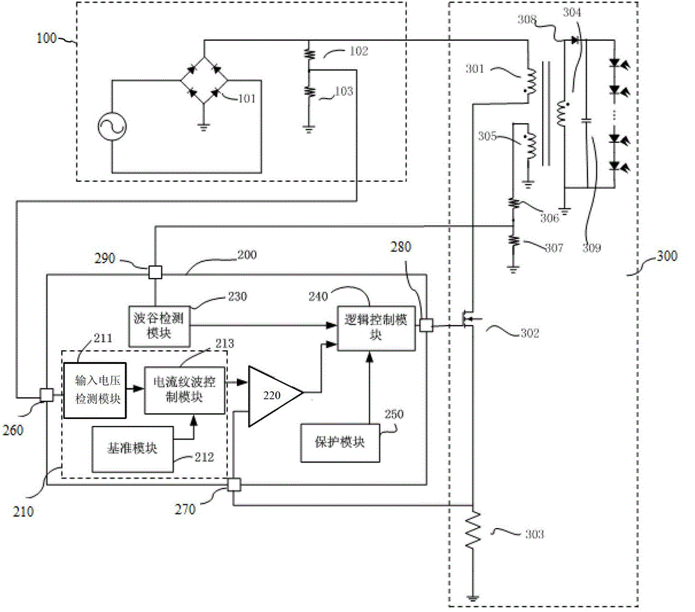
[0041] In the first embodiment of the LED driver chip of the present invention, see figure 1 , the LED driver chip 200 includes:

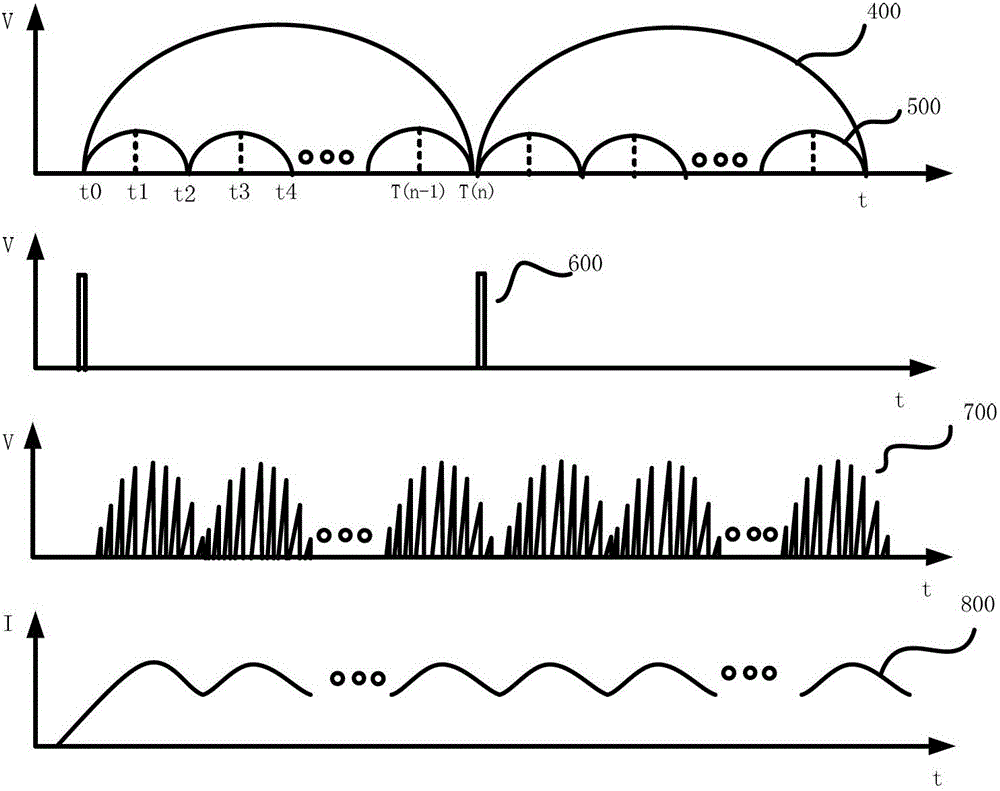
[0042] A sampling control module 210 that samples the peak value of the input AC voltage and outputs a current reference curve whose frequency is at least twice the frequency of the input AC;

[0043] Receiving the voltage value of the main-stage inductance series resistance of the peripheral drive circuit, receiving the current reference curve output by the sampling control module 210, comparing the voltage value of the main-stage inductance series resistance of the peripheral drive circuit with the corresponding voltage value on the current reference curve, and outputting the comparison result Comparator 220;

[0044] A logic control module 240 that receives the comparison result output by the comparator 220 and outputs a...


PUM


Abstract

Provided is an LED driving circuit, comprising a rectifying circuit (100), an LED power supply circuit (300) and an LED driving chip (200), wherein the LED driving chip (200) can generate a current reference with a frequency at least twice the frequency of the alternating current output by the rectifying circuit curve, and control the LED power supply circuit (300) to provide the LED lamp with a current consistent with the frequency of the current reference curve. Also provided is an LED driving chip (200), capable of generating a current reference curve whose frequency is at least twice the frequency of the input alternating current, and controlling peripheral circuits to provide LED lights with current consistent with the frequency of the current reference curve. The LED driving circuit and the LED driving chip of the solution can suppress the low-frequency output current ripple, solve the low-frequency flickering problem in the process of supplying power to the LED, and have simple design, low production cost and high working reliability.

Description

technical field [0001] The invention relates to the technical field of LEDs, and more specifically, to an LED driving circuit and an LED driving chip. Background technique [0002] Current AC-to-DC (AC / DC) LED drive circuits are divided into single-stage and two-stage. The output current of the two-stage circuit has no low-frequency ripple, but the cost is relatively high. Low-cost single-stage AC-to-DC LED driver circuits have low-frequency ripple at AC frequencies after the larger output is rectified. For example, the AC frequency input to the AC-to-DC LED drive circuit is 100Hz. If there is AC power with a frequency below 120Hz in the AC power supplied to the LED, the LED light will flicker (flickernoise). This low-frequency flicker can be clearly seen with mobile phones, video cameras and other devices. If the DC output is used, the power frequency ripple can be reduced and a stable output can be provided to the LED lamp, but the circuit must be connected in parallel ...

Claims


Application Information

Patent Timeline
Patent Type & Authority Patents(China)
IPC IPC(8): H05B37/02
CPCH05B45/385H05B45/382H05B45/37
Inventor 叶军高铭坤王莉
Owner 深圳小墨智能科技有限公司
Why Eureka
Try Eureka