

Storage cabinet with base frame
A storage cabinet and base frame technology, applied in the storage cabinet field, can solve the problems of restricting the structural design and use of the storage cabinet, unfavorable appearance and cost saving, easy deformation of the assembled cabinet, etc., so as to achieve easy quality control and production. The effect of low process difficulty and cost saving
- Summary
- Abstract
- Description
- Claims
- Application Information
AI Technical Summary
Problems solved by technology
Method used
Image

Examples
Embodiment 1
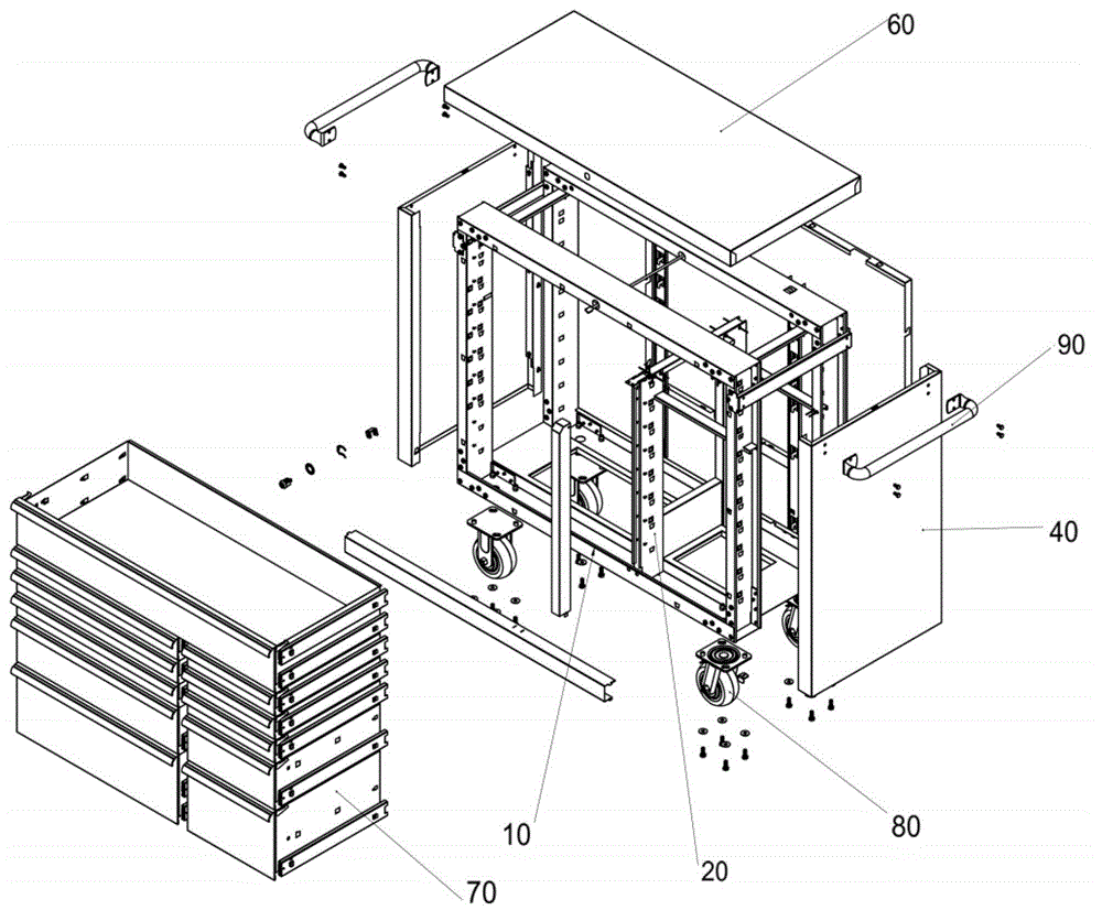
[0035] The locker of this embodiment, its explosion diagram is as follows figure 1 shown. The locker includes a base frame 10 for forming a skeleton of the locker and cabinet accessories, and the cabinet accessories are arranged on the base frame 10 . The locker uses the base frame 10 as a skeleton, and the cabinet accessories of the locker are installed on the base frame 10. The locker has high mechanical strength, good bearing capacity, and is not easily deformed. In addition, the manufacturing technology of the locker is less difficult. After the base frame is assembled, other parts can be erected on the base frame. There is no need for tools such as jigs for positioning, and the quality of the locker is easy to control. Cabinet accessories such as the top panel, side panel and back panel are only for decoration, not as a support for the locker, so the locker can be made of different materials, and the design forms are more diverse, which is conducive to the design of beau...
Embodiment 2
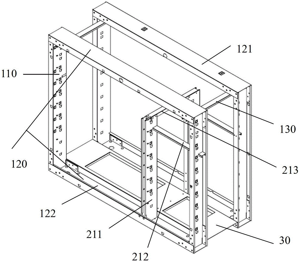
[0047] The locker in this embodiment includes a base frame 10 for forming a skeleton of the locker and cabinet accessories, and the cabinet accessories are arranged on the base frame 10; however, the locker does not include an inner frame body. The structure of the pedestal 10 is as image 3 As shown, its explosion diagram is shown as Figure 4 As shown; the column 110 and the cross bar 120 are connected to form a frame, and the frame refers to two or more frames arranged in parallel, and the bottom plate 30 is arranged between the frames and connected with the frames. The crossbar 120 includes an upper crossbar 121 and a lower crossbar 122; both ends of the connecting rod 130 are respectively connected to adjacent frames. The upright column 110 is connected to the cross bar 120 through the first connecting piece; the connecting rod 130 is connected to the adjacent frame through the second connecting piece.
[0048] The connection between the upright post 110 and the cross b...
Embodiment 3
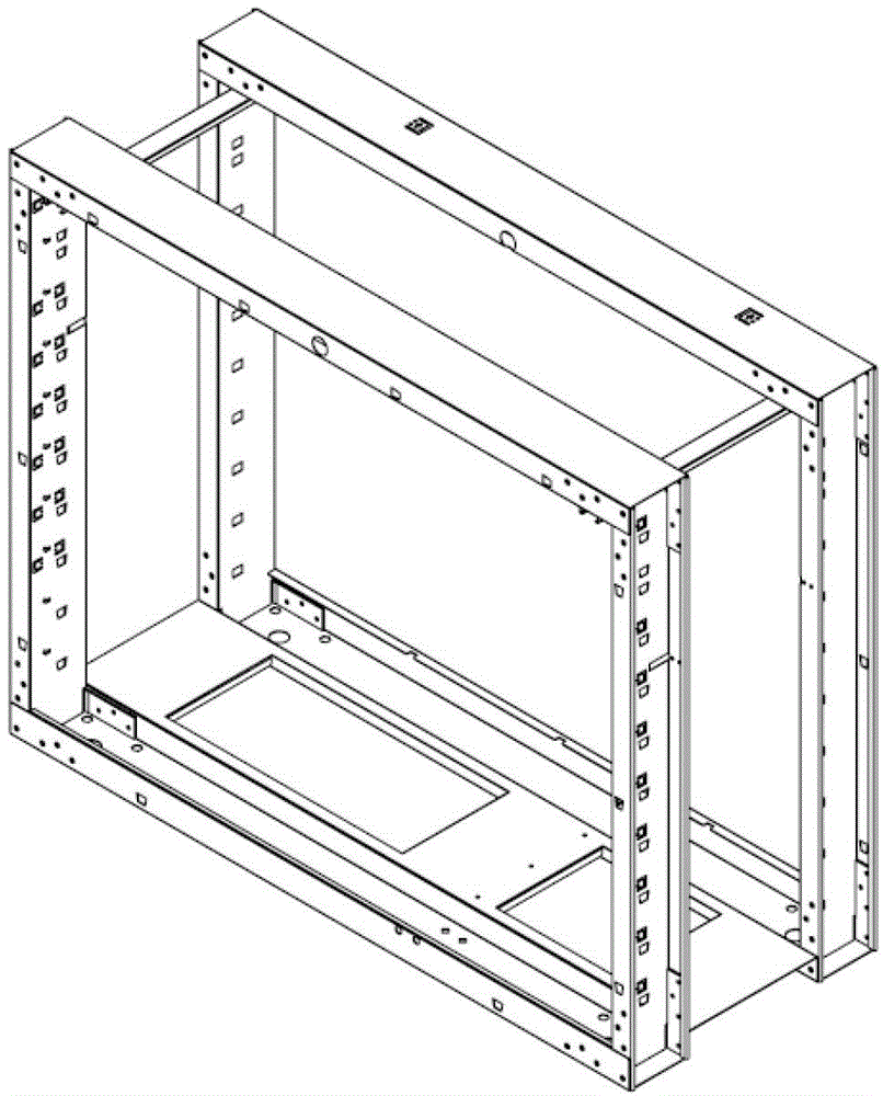
[0052] The locker in this embodiment includes a base frame 10 and cabinet accessories, and the locker does not include an inner frame body. The structure of the pedestal 10 is as Figure 6 As shown; the difference between the locker in this embodiment and the locker in Embodiment 2 is that the upper cross bar 121 is connected with the column 110 in a buckle manner; the two ends of the connecting rod 130 are respectively connected to the adjacent frame That is, the two ends of the connecting rod 130 are respectively connected to the adjacent upright post 110 , and the connecting rod 130 and the upright post 110 are fixedly connected by buckling.
[0053] The structure of other parts of the present embodiment locker is the same as embodiment two.
PUM
 Abstract
Description
Claims
Application Information