Novel efficient dewatering bin and dewatering method

A dehydration silo, high-efficiency technology, applied in separation methods, chemical instruments and methods, filtration and separation, etc., can solve the problems of clogging of dehydration silo, small dehydration area, low dehydration efficiency, etc., to achieve smooth drainage, prolong service life, and dehydration efficiency. added effect

Active Publication Date: 2013-10-02
江苏坤辰科技有限公司
View PDF7 Cites 5 Cited by
  • Summary
  • Abstract
  • Description
  • Claims
  • Application Information

AI Technical Summary

Problems solved by technology

Such a dehydration chamber only includes the dehydration surfaces on both sides, the overall dehydration area is small, the equipment is heavy, the installation accuracy is high, and the dehydration efficiency is low. Pollution of the environment; at the same time, since the slag enters the funnel-shaped dehydration chamber under the beam, there is no secondary dehydration facility, so the dehydration chamber under the beam is prone to blockage

Method used


Image

  • Novel efficient dewatering bin and dewatering method
  • Novel efficient dewatering bin and dewatering method
  • Novel efficient dewatering bin and dewatering method

Examples


Embodiment Construction

[0020] The present invention will be further described below in conjunction with the embodiments and accompanying drawings.

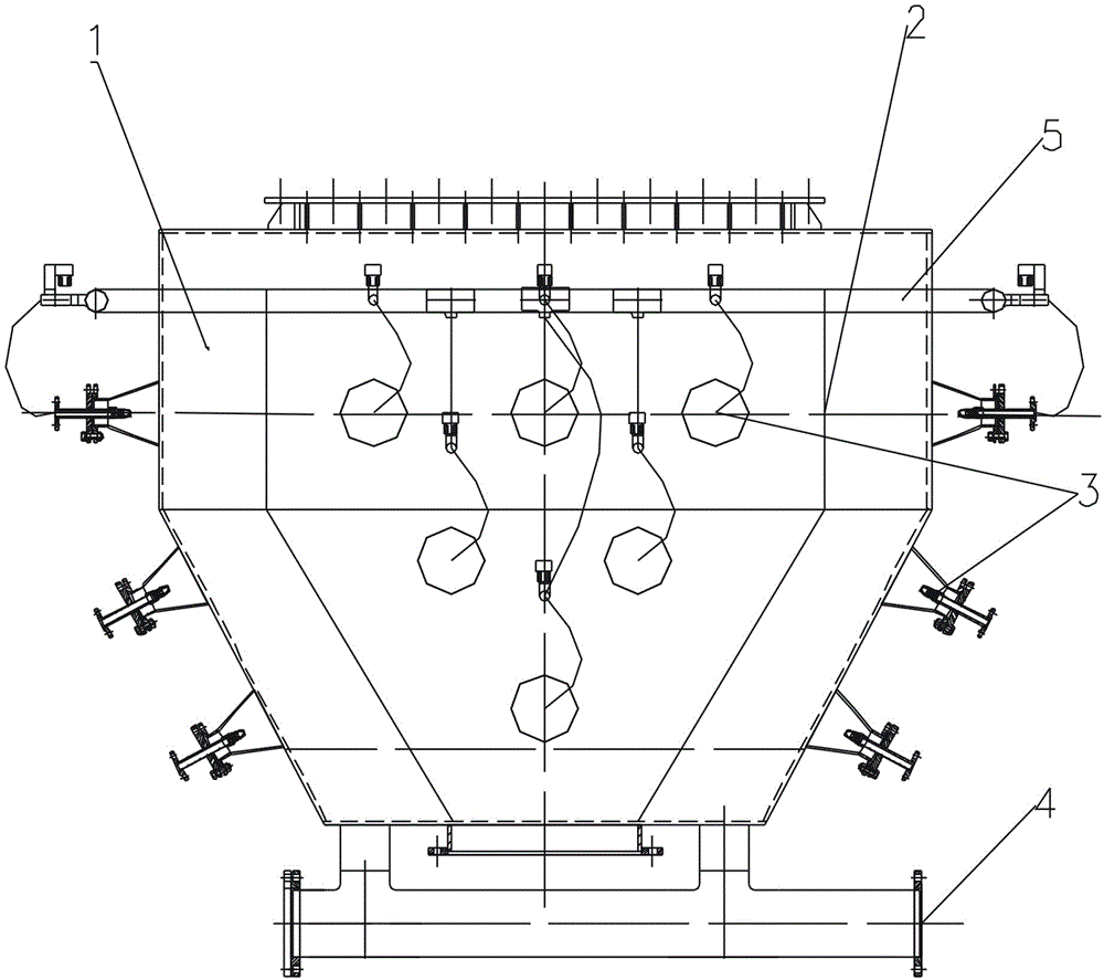
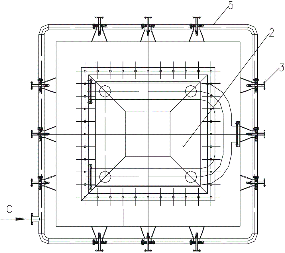
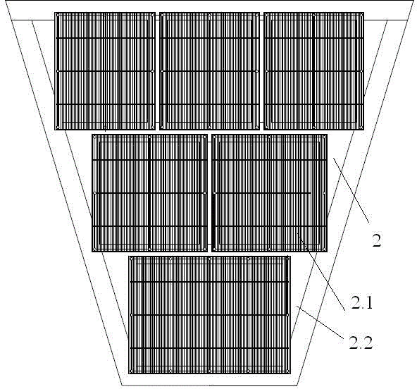
[0021] Such as Figure 1-3 The new high-efficiency dehydration chamber shown is characterized in that: the dehydration chamber is independently installed under the water slag chamber in a single chamber; it is mainly composed of a shell 1, a dehydration plate 2, a recoil cleaning valve 3, a drain pipe 4, and a water inlet pipe 5 The upper part of the shell 1 is a square cylinder, the lower part is connected from top to bottom to form a funnel-shaped tetrahedron, and the bottom is flat and provided with a bottom opening; the dehydration plate 2 has the same shape as the shell 1 and is placed in the shell 1 at intervals; The top and bottom openings of the shell 1 are provided with flanges, the top flange is connected to the interface of the upper water slag bin, and the bottom flange is connected to the slag discharge device; a plurality of recoil cleanin...


PUM


Abstract

The invention discloses a novel efficient dewatering bin and a dewatering method. The novel efficient dewatering bin is independently mounted below a grain slag bin in a single bin manner, and mainly comprises a casing, dewatering plates, a plurality of backflushing and cleaning valves, water drainage pipes and a water inlet pipe, wherein a square column body is arranged at the upper part of the casing, a funnel-shaped tetrahedron is formed at the lower part of the casing, and the bottom of the casing adopts a plane surface and is provided with a bottom opening; the dewatering plate and the casing are the same in shape, and are arranged in the casing at interval; flanges are arranged at both the top and the bottom opening of the casing; the backflushing and cleaning valves are arranged on the outer walls at the periphery of the casing, the water spraying direction of the backflushing and cleaning valves are perpendicular to the plate faces of the dewatering plates at corresponding parts; the water drainage pipes are arranged at the bottom of the dewatering bin and in the positions of the gaps between the dewatering plates and the casing. Grain slag dewatering area inside the bin can be maximized, the water draining is smooth, and the grain slag dewatering efficiency is enhanced. The single dewatering bin manner is adopted, so that another bin can not be mounted after one bin is mounted due to manufacturing errors or deformation can be avoided. The backflushing and cleaning valves ensure complete covered flushing of the stainless steel dewatering plates, and the service lives of the dewatering plates are prolonged.

Description

technical field [0001] The invention mainly belongs to the technical field of iron and steel metallurgical equipment, and can be widely applied to a blast furnace slag storage and transportation system. Background technique [0002] Slag storage and transportation facilities, as a low-cost storage and transportation method, are widely used in the slag processing line of blast furnaces. The dehydration bin is used as a secondary dehydration device for slag in the slag storage and transportation facility, which can effectively reduce the moisture content of slag and minimize the pollution of slag to the surrounding environment during transportation. [0003] The existing dehydration bins are generally two dehydration bins arranged side by side, and the tops of the two dehydration bins are connected and lifted by a beam. There are vertical side walls between the two sides below the top beam and the dehydration bins. Several small holes form the dewatering surface, and the dehy...

Claims


Application Information

Patent Timeline
IPC IPC(8): B01D29/03B01D29/68
Inventor 刘安全万汉英
Owner 江苏坤辰科技有限公司
Why Eureka
Try Eureka