Automatic welding tool for valve

An automatic welding and valve technology, applied in welding equipment, auxiliary welding equipment, welding/cutting auxiliary equipment, etc., can solve the problems of inconvenient rotation, low welding quality and efficiency, etc., to improve welding efficiency and quality, easy to fix and the effect of rotation

Active Publication Date: 2013-10-02
VELAN VALVE SUZHOU
View PDF6 Cites 1 Cited by
  • Summary
  • Abstract
  • Description
  • Claims
  • Application Information

AI Technical Summary

Problems solved by technology

[0004] The technical problem to be solved by the present invention is how to solve the problem that the valve

Method used


Image

  • Automatic welding tool for valve
  • Automatic welding tool for valve
  • Automatic welding tool for valve

Examples


Embodiment Construction

[0029] The specific implementation manners of the present invention will be further described in detail below in conjunction with the accompanying drawings and embodiments. The following examples are used to illustrate the present invention, but are not intended to limit the scope of the present invention.

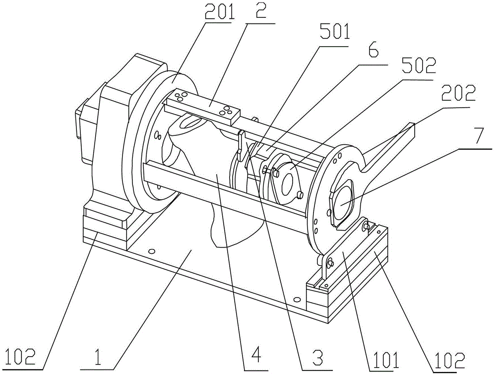
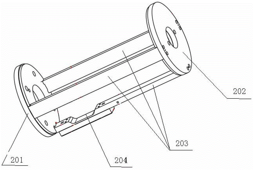
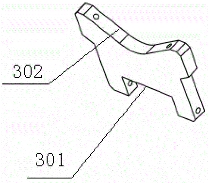
[0030] Such as Figure 1 to Figure 3 The shown valve automatic welding tooling includes: a base 1 , a tooling main frame 2 and a pressing piece 3 . The tooling main frame 2 is provided with a first turntable 201 and a second turntable 202 with a through hole, and the first turntable 201 and the second turntable 202 are connected by three support plates 203 to form a frame that can accommodate valves. The frame is used to support the valve and drive the valve to rotate. The distance between the support plates 203 should be set according to the structure of the valve, so that the valve can not shake after being put in. And according to the different shapes of the valve, t...


PUM


Abstract

The invention discloses an automatic welding tool for a valve, which relates to the technical field of machining, and includes a base, a support seat, a tool main frame and a lining, wherein the base is provided with a motor; the support seat is arranged on the base; the tool main frame further includes a first rotary table and a second rotary table; the first rotary table is connected with a transmission part of the motor; the second rotary table and the first rotary table are connected through a support plate to form a frame body used for supporting and fixing the valve; the second rotary table is mounted on the support seat; the lining includes a first connecting surface and a second connecting surface; a sleeve hole is formed in the first connecting surface of the lining, so that the first connecting surface can be sleeved with the end port of the valve and used for fixing the valve; the second connecting surface of the lining is detachably connected with the second rotary table; through holes are formed in the first connecting surface of the lining and the second rotary table. The automatic welding tool for the valve can be used for fixing and rotating the to-be-welded valve conveniently, and meets the requirements for flexible rotation of the valve during the automatic welding production of the valves, thereby improving the welding efficiency.

Description

technical field [0001] The invention relates to the technical field of mechanical processing, in particular to an automatic welding tool for valves. Background technique [0002] Manual welding is generally used in the valve welding process, usually directly on the workbench. Since the valve cannot be effectively fixed, workers need to turn the valve repeatedly, which is time-consuming and laborious. Therefore, the welding efficiency is low and cannot meet the new requirements of valve production. The use of automatic welding can greatly improve production efficiency, but an automatic valve welding tool that can rotate flexibly is needed. Contents of the invention [0003] (1) Technical problems to be solved [0004] The technical problem to be solved by the present invention is how to solve the problems that the valve cannot be rotated conveniently and the welding quality and efficiency are not high during the welding process. [0005] (2) Technical solution [0006] I...

Claims


Application Information

Patent Timeline
IPC IPC(8): B23K37/047
Inventor 沈国熙孙建昆陈甫陈俊荣李纪宏陈铁
Owner VELAN VALVE SUZHOU
Why Eureka
Try Eureka