Continuous coating equipment

A coating and equipment technology, applied in the field of continuous coating equipment for fertilizer granules, can solve the problems of incomplete discharge, dead angle, unstable fertilizer coating quality, etc., and achieve the effect of uniform airflow circulation and uniform spraying without dead angle.

Active Publication Date: 2013-10-02
BEIJING ACADEMY OF AGRICULTURE & FORESTRY SCIENCES
View PDF9 Cites 4 Cited by
  • Summary
  • Abstract
  • Description
  • Claims
  • Application Information

AI Technical Summary

Problems solved by technology

When collecting coated fertilizer granules, it is necessary to close the venetian blind 25 that is placed obliquely between the outer wall of the draft tube 23 and the coating tower 20 to block the circulation of the fertilizer granules. In the above structure, the venetian blind 25 is used to open , closed form, so the internal cross-section of the coating tower 20 must be set to a square to be realized, and the setting of the square coating tower 20 and the venetian blind 25 causes the problem of uneven air circulation, especially the four corners will Forming the dead angle of the suspended accumulation of fertilizer particles will cause the fertilizer particles in the square coating tower 20 to be sprayed evenly, and also cause the fertilizer particles to be attached to the edge of the venetian blind 25, forming a gap when the venetian blind 25 is closed. Nearly and seriously affect the normal collection of fertilizer granules
Furthermore, since the discharge surface is a flat surface, and the connected output pipe 26 is a circular rotating impeller discharge device, the problem of incomplete discharge results in repeated coating of residual fertilizer, making the quality of fertilizer coating unstable

Method used


Image

  • Continuous coating equipment
  • Continuous coating equipment
  • Continuous coating equipment

Examples


Embodiment Construction

[0014] The present invention will be described in detail below in conjunction with the accompanying drawings and embodiments.

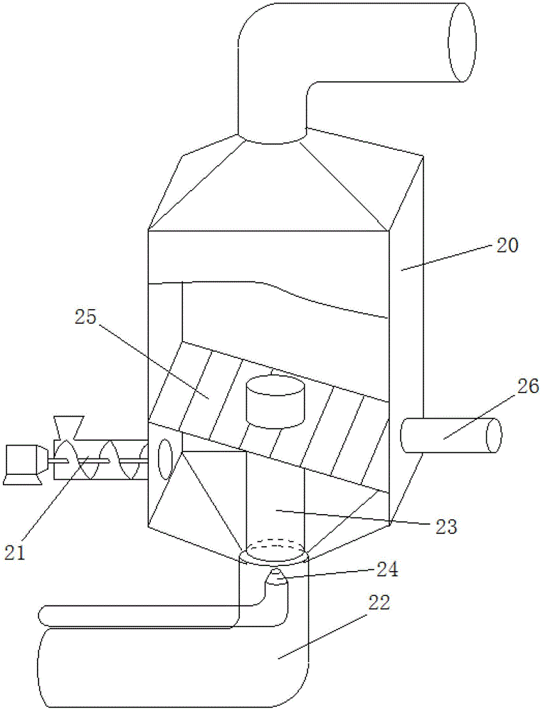
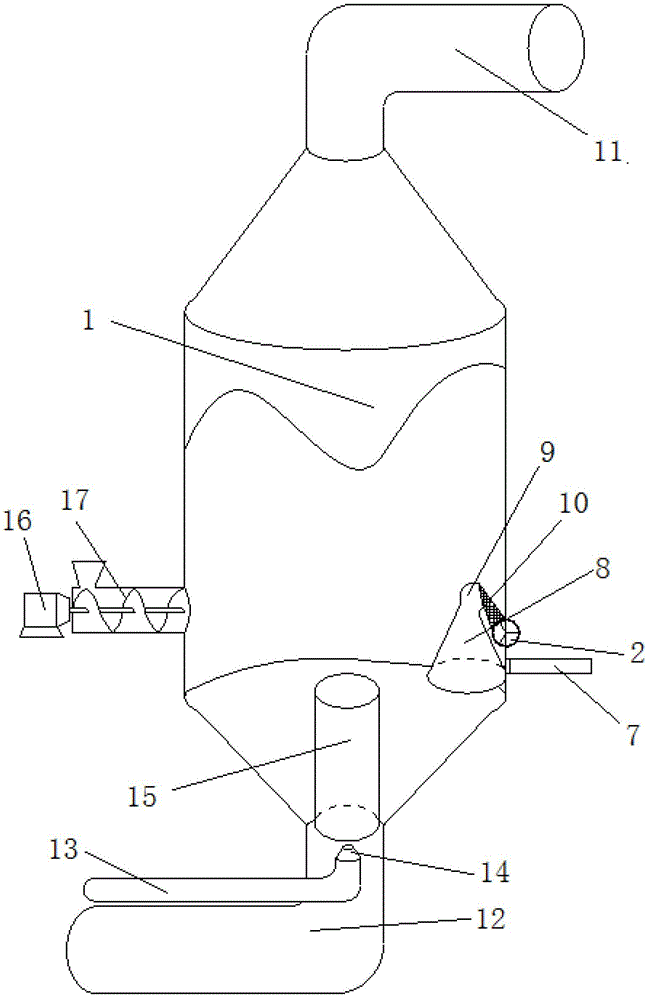
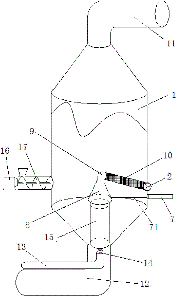
[0015] Such as figure 2 , image 3 As shown in , the present invention comprises a circular coating tower 1, the side wall of the middle part of the coating tower 1 is provided with a discharging cylinder 2, and a rotating impeller 4 driven by a motor 3 is arranged in the discharging cylinder 2, and the outer side of the discharging cylinder 2 The oblique lower part of the wall is provided with a discharge opening 5, and the oblique upper part of the inner side wall of the discharging cylinder 2 is provided with a connection port 6 (such as Figure 4 shown). The circular coating tower 1 below the discharging cylinder 2 is provided with a hydraulic cylinder 7 that can be adjusted up and down, and the piston 71 of the hydraulic cylinder 7 passes through the side wall of the circular coating tower 1 to connect with a frustum-shaped The material recei...


PUM

PropertyMeasurementUnit
diameteraaaaaaaaaa

Abstract

The invention relates to continuous coating equipment. Characteristics of the equipment are that: the continuous coating equipment comprises a cylindrical coating tower; a material canister is arranged on the sidewall of the coating tower, and is provided with a rotating impeller driven by a motor; the outer sidewall of the material canister is provided with a feed outlet, and the inner sidewall of the material canister is provided with a connection port; the cylindrical coating tower is provided with a hydrocylinder which can be adjusted and moved up and down; a piston of the hydrocylinder penetrates the sidewall of the cylindrical coating tower, and is connected to a frustum-shaped feed gathering cover, wherein the upper part of the feed gathering cover is smaller, and the lower part of the feed gathering cover is bigger; the feed gathering cove is connected to one end of a stretch hosepipe through an elbow, and the other end of the stretch hosepipe is connected to the connection port of the material canister; the top of the cylindrical coating tower is connected with an exhaust channel, and the bottom of the cylindrical coating tower is connected with a hot wind channel; a solution jet pipe is inserted into the hot wind channel; the top port of the solution jet pipe is connected with a nozzle; the nozzle and the feed gathering cover are connected by a cylindrical guide pipe, and the cylindrical guide pipe is fixed by a support; and the outer wall of the bottom of the cylindrical coating tower is connected with a feed outlet of an auger feeding device which is driven by a motor. The continuous coating equipment can be widely used for coating various particles.

Description

technical field [0001] The invention relates to a fertilizer coating equipment, in particular to a continuous coating equipment for fertilizer granules. Background technique [0002] Generally, controlled-release fertilizers mostly use polymer coatings with low water permeability to achieve controlled release of fertilizer nutrients. The production process is generally to spray the solvent containing the coating material on the fertilizer particles in the fluidized bed, the solvent is volatilized in the hot air, and the coating material is wrapped on the surface of the fertilizer to form a resin film with low moisture permeability. The water in the soil enters the fertilizer granules through the resin film, and dissolves the nutrients out of the film to supply the crops for absorption. The dissolution rate of the fertilizer in the film is the effective release rate of fertilizer nutrients. The controlled release rate of nutrients is controlled by the coating. . Such as fi...

Claims


Application Information

Patent Timeline
Patent Type & Authority Applications(China)
IPC IPC(8): C05G3/00
Inventor 谷佳林徐秋明曹兵刘宝存赵同科邹国元张宜霞刘善江杨宜斌李鸿雁
Owner BEIJING ACADEMY OF AGRICULTURE & FORESTRY SCIENCES
Why Eureka
Try Eureka