Siphon head for cleaning swimming pool

A technology of swimming pool and siphon head, applied in the field of siphon head, can solve the problems of unbalance and small siphon force

Active Publication Date: 2013-10-02
NINGBO DONGCHUAN SWIMMING POOL EQUIP
View PDF5 Cites 3 Cited by
  • Summary
  • Abstract
  • Description
  • Claims
  • Application Information

AI Technical Summary

Problems solved by technology

However, the siphon head of the above structure has the following disadvantages in actual use: Figure 5 , there are four water outlet holes 05. According to the basic principles of fluid mechanics, due to the fast flow rate at the water outlet holes 05, a negative pressure zone will be formed around the fluid, and the pressure around each water outlet hole 05 is from near to far. Decreasing, as shown in the figure, it includes four high-pressure areas A, B, C, and D, and a low-pressure area E with very low pressure will be formed in the center of these four high-pressure areas, so that when the fluid flows from the cylinder 01 to the When spraying out of the cylinder, under the action of unbalanced pressure, part of the sprayed fluid will be sucked into the cylinder under the action of low pressure to form a backflow, further combined with the attached Image 6 , since the pipe diameter of the cylinder 01 from the sewage suction port 04 to the sewage outlet 03 increases sequentially, when it reaches the sewage outlet 03, it already has an obvious bell-mouth structure, and each of the cylinders The two horizontal sections are all circular, that is to say, the cylinder body is an annular bell mouth with increasing pipe diameters from the sewage suction port 04 to the sewage outlet 03. This structure acts as a siphon to guide the fluid from the water outlet 05 After being sprayed out, it will be sprayed outwards in a diffuse shape under the guidance of the inner wall of the cylinder 01, and then combined with the attached Figure 5 In the pressure distribution diagram, the siphon force corresponding to the central position E area of ​​the cylinder 01 is relatively small, while the siphon force corresponding to the four peripheral areas A, B, C, and D is relatively large, so that part of the fluid that has been ejected is re-absorbed Returning to the cylinder 01 to form a backflow 012, the backflow 012 not only counteracts the flow velocity of the fluid sprayed outwards, but also easily forms a swirl with the fluid sprayed outwards, so it will be in the inner wall of the cylinder and the central area A vortex is generated at the junction, and the generation of the vortex greatly changes the flow velocity and direction of the guided water, and the siphon force of the siphon head further decreases
Also caused the siphon head in the prior art to have the defect that the siphon force is small all the time

Method used


Image

  • Siphon head for cleaning swimming pool
  • Siphon head for cleaning swimming pool
  • Siphon head for cleaning swimming pool

Examples


Embodiment Construction

[0023] The present invention will be described in further detail below in conjunction with the accompanying drawings.

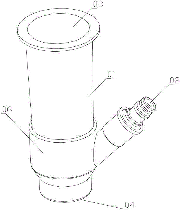
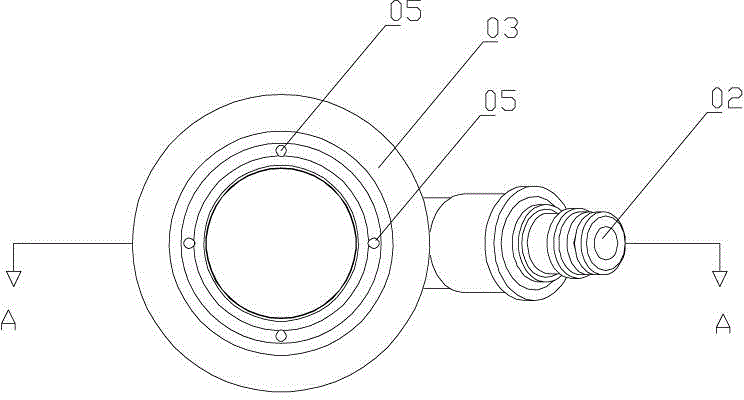
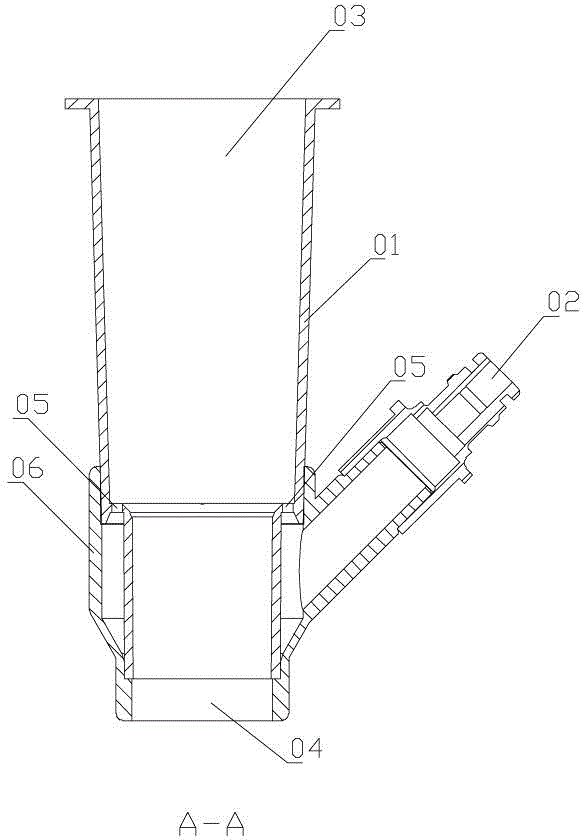
[0024] combined with Figure 7 to attach Figure 10 , a siphon head for cleaning swimming pools, it includes a cylinder 1, the upper end of the cylinder 1 is a sewage outlet 3, the lower end is a sewage suction port 4, the side wall is provided with a water inlet 2, and the water inlet 2 is connected to a water outlet The hole 6, the water outlet hole 6 is located on the inner wall of the cylinder 1, and the water outlet direction is towards the sewage outlet 3; the water outlet hole 6 is one, and the sewage outlet 3 is connected with a cover 5, and the cover 5 Just above the water outlet hole 6, there is a gap between 1 / 4~1 / 2 of the total area of ​​the cover. The cover 5 is clamped with the sewage outlet 3, the cover 5 is provided with a clamping protrusion 9, and the barrel 1 is provided with a clamping hole 10 for engaging with the clamping protrusion. ...


PUM


Abstract

The invention provides a siphon head which is larger in siphon force and used for cleaning a swimming pool. The siphon head for cleaning the swimming pool comprises a cylinder body (1), wherein a sewage outlet (3) is formed in the upper end of the cylinder body (1), a sewage suction mouth (4) is formed in the lower end of the cylinder body (1), a water inlet (2) is formed in the side wall of the cylinder body (1), the water inlet (2) is communicated with a water outlet hole (6), the water outlet hole (6) is formed in the inner wall of the cylinder body (1), and the water outlet direction faces towards the sewage outlet (3). The siphon head for cleaning the swimming pool is characterized in that the number of the water outlet hole (6) is one, the sewage outlet (3) is connected with a cover (5), a gap is reserved in the position, over the water outlet hole (6), of the cover (5), and the size of the gap is from one fourths to one seconds of the area of the cover.

Description

technical field [0001] The invention relates to a siphon head for cleaning swimming pools. Background technique [0002] In the prior art, there is a cleaner that uses the principle of siphon to clean the bottom of the swimming pool. It mainly includes two parts: a siphon head and a cleaning head. figure 1 to attach Figure 4 , the siphon head includes a cylinder 01, the upper end of the cylinder 01 is the sewage outlet 03, the lower end is the sewage suction port 04, and the lower part of the cylinder 01 is provided with an annular water conduction chamber 06, and the annular water conduction chamber 06 is provided with a plurality of water outlet holes 05, and the annular water conducting chamber 06 is also connected with a water inlet 02. The water outlet holes 05 are evenly distributed on the upper end surface of the annular water conducting chamber 06 and are located in the cylinder body 01; the cleaning head includes a joint 07, a handle connection part 08 and a roll...

Claims


Application Information

Patent Timeline
Patent Type & Authority Applications(China)
IPC IPC(8): E04H4/16
Inventor 何怀忠
Owner NINGBO DONGCHUAN SWIMMING POOL EQUIP
Why Eureka
Try Eureka