Gob-side entry retaining flexible infilled wall body structure and filling method thereof

A technology of wall structure and roadway retention, which is applied in the direction of filling, earthwork drilling, safety devices, etc., can solve the problems of gas leakage, complicated process, deformation of surrounding rock, etc. in the support body, and achieve the prevention of lateral deviation, The effect of overcoming polluted environment and inhibiting subsidence

Inactive Publication Date: 2015-04-08
ANHUI UNIV OF SCI & TECH
View PDF9 Cites 0 Cited by
  • Summary
  • Abstract
  • Description
  • Claims
  • Application Information

AI Technical Summary

Problems solved by technology

[0003] In the past, there were mainly two modes of entry retention on hard roofs: the first mode used filling rigid materials (σ c ≥4MPa), the roadway is mainly "supported", and its disadvantage is that the rigid material cannot adapt to the dynamic load caused by the movement of the roof, so that the support body is easily fractured, causing gas leakage or even ignition, or roadway instability leads to roadway retention Failed; the second mode of filling flexible materials (generally filling crushed gangue) is mainly "protection", and its disadvantage is that the stress-strain relationship of the gangue bearing pressure and the coordination relationship between the filling body and the movement of the overburden rock have not been grasped. Quantitative support design cannot be carried out, which may easily cause large deformation of the surrounding rock and excessive roof sinking, resulting in roof fall in the roadway. In order to effectively avoid the above problems, the method of blasting and breaking the roof was usually used in the past, but the process is complicated and the construction is difficult. Large, which limits the popularization and application of gob-side entry retention

Method used


Image

  • Gob-side entry retaining flexible infilled wall body structure and filling method thereof
  • Gob-side entry retaining flexible infilled wall body structure and filling method thereof
  • Gob-side entry retaining flexible infilled wall body structure and filling method thereof

Examples


Embodiment 1

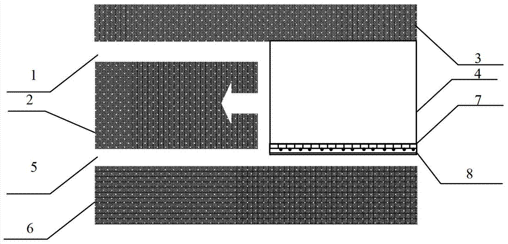
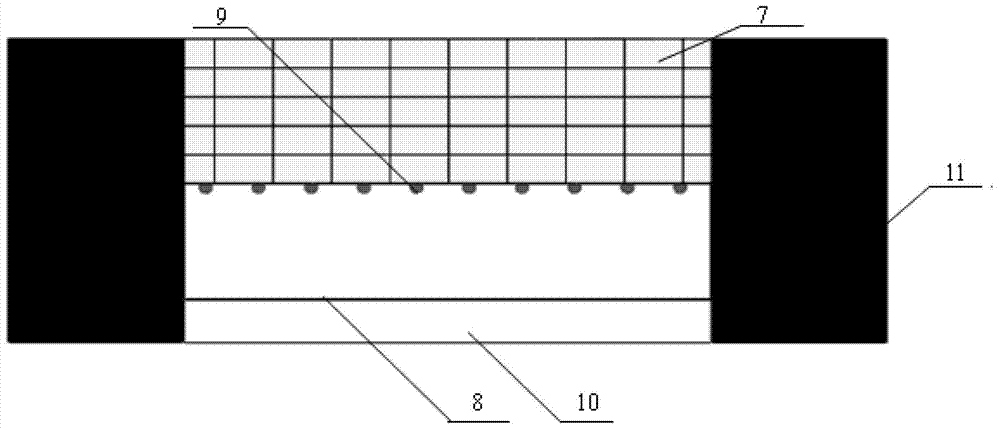
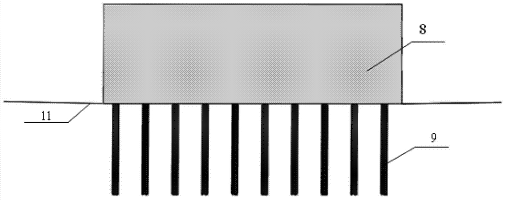
[0039] Such as Figure 1-Figure 5As shown, the gobside retaining flexible filling wall structure of the present invention includes a filling wall 8 and bagged gangue 7 and threaded anchor rods 9 arranged inside the filling wall 8 . The filling wall is located in the goaf 4 of the working face between the air return roadway 1 and the transportation roadway 5, which is close to the transportation roadway 5, and the roadway between the coal body 3 on the upper working face and the coal body 2 on the working face is the return airway. Air lane 1, the roadway between the coal body 6 of the lower working face and the coal body 2 of this working face is the transport lane 5. There are multiple bagged gangue 7 and threaded anchor rods 9, the laying height of the bagged gangue 7 is the height of the roadway, and the threaded anchor rod 9 is in contact with the bagged gangue 7 on the side of the roadway near the transportation lane 5 And vertically buried in the roadway floor 11.

Embodiment 2

[0041] On the basis of Example 1, the size of a single bagged gangue 7 is length*width*height=450mm*450mm*150mm, and the gangue particle diameter inside it is less than 20mm; the exposed part of the threaded anchor rod is 800mm long. -1200mm; the distance between the plurality of threaded anchor rods 9 is 450mm, and each of the threaded anchor rods is just in the middle of each bottom bagged gangue; the distance between the bagged gangue on the side of the transportation lane 5 is 7 A filling wall formwork 10 is erected at a distance of 500-750 mm; the filling wall 8 includes sand, cement, and coal mine special filling quick-setting curing cement powder.

[0042] The laying width of the bagged gangue 7 is determined by the force balance formula of the lateral overlying rock structure model, namely:

[0043] W = 4 L m + 4 R q - ...

Embodiment 3

[0051] A method for flexible wall filling in gob-side retaining, comprising the following steps:

[0052] (1) Firstly, the underground gangue is directly transported to the underground crushing chamber through the belt conveyor and crushed to form gangue with a suitable particle size of less than 20mm, and the formed gangue is loaded into a box whose size is length*width*height=450mm*450mm*150mm in a woven bag;

[0053] (2) Pile up bagged gangue 7 along the goaf, lay interlaced filling between each layer for roadside support, and form a preliminary filling wall skeleton;

[0054] (3) After the above steps are completed, a row of threaded anchor rods 9 through the wall are drilled at the side of the roadway side of the bagged gangue 7 near the transport lane 5. The exposed part of the threaded anchor rods is 800-1200mm in length, and two adjacent The distance between the threaded anchor rods 9 is 450mm, and each of the threaded anchor rods is just in the middle of each bottom ...


PUM


Abstract

The invention discloses a gob-side entry retaining flexible infilled wall body structure which comprises an infilled wall body, as well as bagged gangue and threaded anchor rods. The laying height of the bagged gangue is the height of a roadway, the threaded anchor rods are in contact with the bagged gangue close to one side of a transportation roadway and is vertically buried in a roadway baseplate, and the exposed part is in the length of 800-1200 mm; the adjacent two threaded anchor rods are 450 mm away from each other; on the transportation roadway side 500-750 mm away from the bagged gangue, an infilled wall body template is erected. As a paste material is wholly filled outside the gangue bags, the flexible infilling body is reinforced into an inclosed solid and deformed with the internal bagged gangue collaboratively, and accordingly, communication between a goaf and harmful gases in the roadway is prevented.

Description

technical field [0001] The invention relates to a gob-side entry retaining flexible filling wall structure and a filling method thereof. The flexible filling wall structure is especially suitable for gob-side entry retaining in medium-thick coal seams under a hard roof. Background technique [0002] After the coal mining face has been mined, the roadway in the section (or lower section) on the original working face is reserved and used when the adjacent working face is mined. The remaining roadway is called gob-side entry retention. After the working face of the upper section of the mining area is mined, the roadway left along the goaf can be used as a return airway when the working face of the lower section is mined. [0003] In the past, there were mainly two modes of entry retention on hard roofs: the first mode used filling rigid materials (σ c ≥4MPa), the roadway is mainly "supported", and its disadvantage is that the rigid material cannot adapt to the dynamic load cau...

Claims


Application Information

Patent Timeline
Patent Type & Authority Patents(China)
IPC IPC(8): E21F15/04
Inventor 成云海张向阳冯飞胜刘柳平朱萌萌任禹
Owner ANHUI UNIV OF SCI & TECH
Why Eureka
Try Eureka