An air distribution device for a circulating fluidized bed boiler

A technology of circulating fluidized bed and air distribution device, applied in the field of air distribution device, can solve the problems of flow deviation of front and rear wall water-cooled tube screens, heat deviation of rear wall water-cooled tube screen, hydrodynamic force, large difference in pipeline resistance, etc. Achieve the effect of reducing thermal deviation and hydrodynamic deviation

Active Publication Date: 2016-03-30
DONGFANG BOILER GROUP OF DONGFANG ELECTRIC CORP
View PDF7 Cites 0 Cited by
  • Summary
  • Abstract
  • Description
  • Claims
  • Application Information

AI Technical Summary

Problems solved by technology

The air distribution device is formed by bending the water-cooled tube panel 15 on the front wall. Because the air-distributing plate 19 water-cooled tube panel absorbs part of the heat released by the fuel combustion in the furnace, there is a certain deviation in the heat load of the front and rear wall water-cooled tube panels. At the same time, due to the large difference in strokes of the working medium in the front and rear wall water-cooled tube panels, this layout structure makes the difference in pipe resistance between the front and rear wall water-cooled tube panels, resulting in the flow rate of the front and rear wall water-cooled tube panels There is a certain deviation
To sum up, the air distribution device is likely to cause certain thermal and hydrodynamic deviations in the water-cooled tube panels of the front and rear walls, which will seriously restrict the development trend of circulating fluidized bed boilers to large capacity and high parameters.

Method used


Image

  • An air distribution device for a circulating fluidized bed boiler
  • An air distribution device for a circulating fluidized bed boiler
  • An air distribution device for a circulating fluidized bed boiler

Examples


Embodiment Construction

[0014] The present invention will be described in further detail below in conjunction with the accompanying drawings.

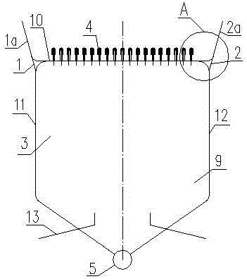
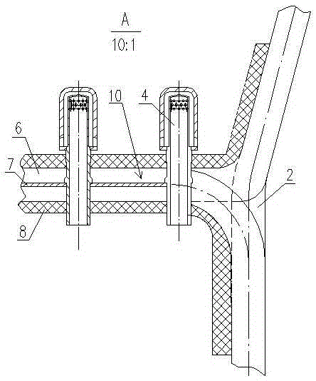
[0015] Such as Figure 2 to Figure 3 As shown, the air distribution device of the circulating fluidized bed boiler includes a front wall water-cooled wall tube panel 1, a rear wall water-cooled wall tube panel 2, left and right side walls 3, several air cap devices 4, and a lower header 5, The front wall water-cooled wall tube panel 1 includes a bent front upper tube panel 1a, a horizontal section tube panel, a front front wall middle tube panel, an inclined front front wall lower tube panel, a rear middle tube panel, and an inclined rear lower tube panel screen; rear wall water wall tube panel 2 includes bent rear upper tube panel 2a, horizontal section tube panel, front middle tube panel, inclined front lower tube panel, rear rear wall middle tube panel, inclined rear rear wall lower tube panel Screen;

[0016] The tube panels 6 of the horizontal section ...


PUM


Abstract

The invention discloses an air distribution device of a circulating fluidized bed boiler. The air distribution device comprises a front water wall panel, a back water wall panel, a left side wall and a right side wall, a plurality of wind cowl devices and a lower header. The front water wall panel comprises a curved front upper panel part, a horizontal panel part, a back middle panel part, and an inclined back lower panel part; the back water wall panel comprises a curved back upper panel part, a horizontal panel part, a front middle panel part, and an inclined front lower panel part. The pipes of the horizontal panel parts of the front and the back water panels are staggered with each, and are coated with fire-resistant and wear-resistant layers; the front middle panel part and the back middle panel part, and the inclined front lower panel part and the inclined back lower panel part are symmetrically arranged respectively, and are coated with the fire-resistant and wear-resistant layers; the ends of the inclined front and the inclined back lower panel part are both connected with the lower header; the plurality of wind cowl devices are arranged on a air distribution plate. The air distribution device is capable of decreasing thermal deviation and hydrodynamic deviation of the front and the back water wall panels, and providing technical support for a development of circulating fluidized bed boilers with high-capacity and high parameters.

Description

technical field [0001] The invention relates to an air distribution device for a circulating fluidized bed boiler. Background technique [0002] With the rapid development of circulating fluidized bed boiler technology, circulating fluidized bed boilers show a trend towards large capacity and high parameters. As an important part of the boiler, the air distribution device has the main functions in the circulating fluidized bed boiler: 1. Support the bed material; 2. Make the air evenly distributed on the cross-section of the entire combustion chamber, and make the bed material and materials uniform Fluidize. The advantages and disadvantages of the structure of the air distribution device affect the combustion performance, safety and economy of the circulating fluidized bed boiler. [0003] At present, the air distribution device is widely used in circulating fluidized bed boilers in my country, and its structure is as follows: figure 1 As shown, it includes the front wall...

Claims


Application Information

Patent Timeline
Patent Type & Authority Patents(China)
IPC IPC(8): F23C10/20
Inventor 刘行磊岳鹏飞龚留升孟庆松周棋郭强郑兴胜
Owner DONGFANG BOILER GROUP OF DONGFANG ELECTRIC CORP
Why Eureka
Try Eureka