
W flame boiler adopting circulating flue gas type slit-type direct-flow pulverized coal burners

A pulverized coal burner, a technology for circulating flue gas, which is applied in the combustion of gaseous fuel and powdered fuel, the combustion of lump fuel and gaseous fuel, the combustion of lump fuel and powdered fuel, etc., can solve the NOx emission The problems of high concentration, high content of combustibles in fly ash, and over-temperature of the water wall of the lower furnace can reduce NOx emissions, reduce the content of combustibles in fly ash, and prolong the burnout process.

Active Publication Date: 2021-08-31
HARBIN INST OF TECH
View PDF10 Cites 0 Cited by
  • Summary
  • Abstract
  • Description
  • Claims
  • Application Information

AI Technical Summary

Problems solved by technology

[0005] The purpose of the present invention is to solve the problems of high NOx emission concentration, poor combustion stability, high fly ash combustible content, overtemperature of the lower furnace water wall, large wall temperature deviation and slagging in the existing W flame boiler, and then provide a W Flame Boiler Using Circulating Flue Gas Slit Type DC Pulverized Coal Burner

Method used


Image

  • W flame boiler adopting circulating flue gas type slit-type direct-flow pulverized coal burners
  • W flame boiler adopting circulating flue gas type slit-type direct-flow pulverized coal burners
  • W flame boiler adopting circulating flue gas type slit-type direct-flow pulverized coal burners

Examples


specific Embodiment approach 1

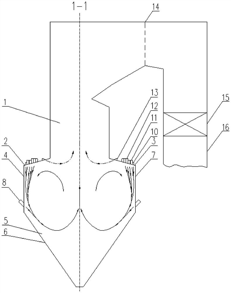
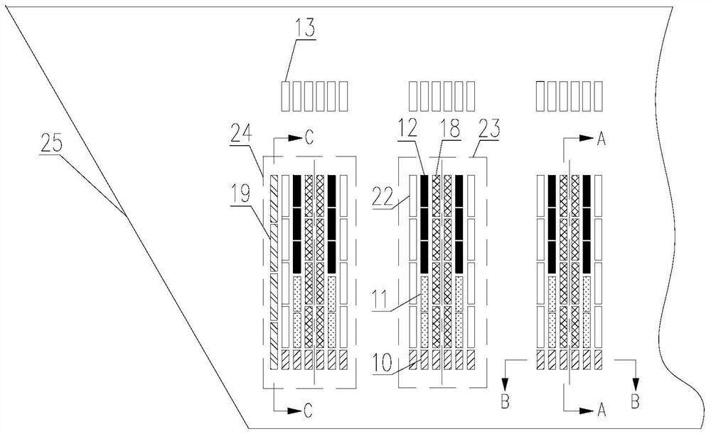
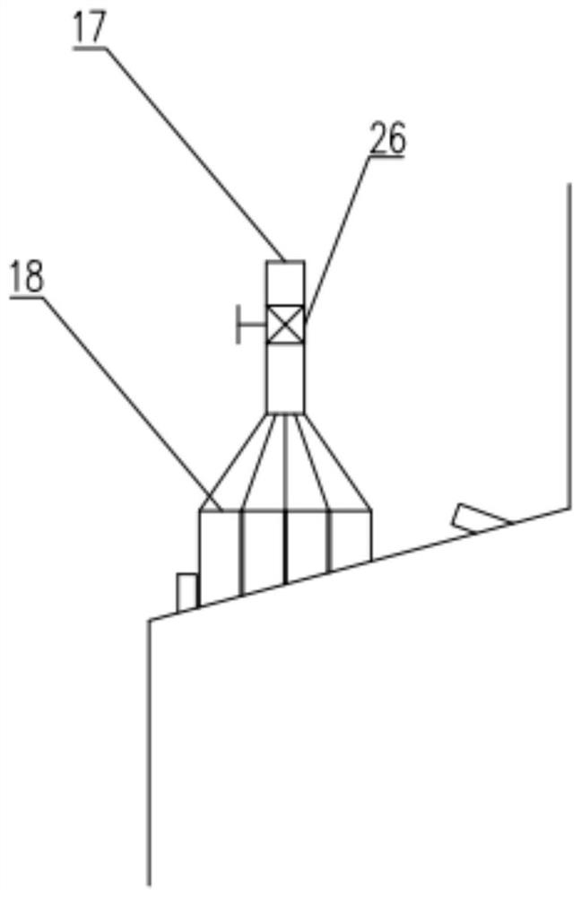
[0031] Specific implementation mode one: combine figure 1 and figure 2 Describe the present embodiment, a W flame boiler adopting circulating flue gas type slit type direct-flow pulverized coal burner in this embodiment, the W flame boiler includes an upper furnace 1 and a lower furnace 5, and the lower furnace 5 includes a front arch 2, Rear arch 3, front wall 4, rear wall 7, cold ash hopper 6 and multiple DC pulverized coal burners, DC pulverized coal burners are circular flue gas gap type DC pulverized coal burners, multiple DC pulverized coal burners It is symmetrically arranged on the front arch 2 and the rear arch 3 with the hearth center line 1-1 as the center, and a plurality of DC pulverized coal burners are all connected to the lower furnace 5, and each DC pulverized coal burner includes a concentrated coal pulverized air flow nozzle 12 , light coal powder airflow nozzle 11, main circulation flue gas nozzle 18, outer circulation flue gas nozzle 10 and secondary air...

specific Embodiment approach 2

[0033] Specific implementation mode two: combination figure 1 and figure 2 Describe this embodiment, the DC pulverized coal burner of this embodiment is divided into two categories, wherein the DC pulverized coal combustion near the wing wall 25 is the side DC pulverized coal combustion 24, and the DC pulverized coal combustion located between the side DC pulverized coal combustion 24 The DC pulverized coal burner is the middle DC pulverized coal combustion 23 .

[0034] In this way, the difference between the side DC pulverized coal combustion 24 and the middle DC pulverized coal combustion 23 is that the side DC pulverized coal combustion 24 is close to the outer side of the wing wall 25, and a boundary circulation flue gas nozzle 19 is arranged to prevent the pulverized coal from being scoured by the air flow. Wing wall 25 water-cooled walls. Other compositions and connections are the same as in the first embodiment.

specific Embodiment approach 3

[0035] Specific implementation mode three: combination figure 2 The present embodiment is described. In this embodiment, a plurality of DC pulverized coal burners arranged on the front arch 2 and the rear arch 3 are equally spaced along the width direction of the furnace.

[0036] Such setting ensures that the gas entering the lower furnace 5 through the direct-flow pulverized coal burner is uniform and comprehensive. Other compositions and connections are the same as those in Embodiment 1 or Embodiment 2.


PUM


Abstract

The invention discloses a W flame boiler adopting circulating flue gas type slit-type direct-flow pulverized coal burners, and relates to the technical field of boiler combustion. The W flame boiler solves the problems that an existing W flame boiler is high in NOx emission concentration, poor in combustion stability, high in fly ash combustible matter content, overtemperature of a water cooling wall of a lower hearth, large in wall temperature deviation and slag bonding. According to the W flame boiler, the plurality of direct-flow pulverized coal burners are symmetrically arranged on a front arch and a rear arch with the center line of a hearth as the center, thin pulverized coal airflow nozzles are arranged on the sides close to the water cooling walls, main circulating flue gas nozzles are arranged on the sides, close to the center lines of the direct-flow pulverized coal burners, of thick pulverized coal airflow nozzles and the thin pulverized coal airflow nozzles, secondary air nozzles are arranged on the sides, away from the center lines of the direct-flow pulverized coal burners, of the thick pulverized coal airflow nozzles and the thin pulverized coal airflow nozzles, and outer circulating flue gas nozzles are arranged on the sides, close to the water cooling walls in the width direction of the hearth. The W flame boiler is used for reducing NOx emission of a hearth outlet, enhancing stable combustion and burnout of pulverized coal, reducing overtemperature and thermal deviation of the water cooling walls of the front wall and the rear wall of the lower hearth, and preventing slag bonding of the water cooling walls.

Description

technical field [0001] The invention relates to the technical field of boiler combustion, in particular to a W-flame boiler adopting a circulating flue gas type gap-type direct-flow pulverized coal burner. Background technique [0002] With the vigorous development of my country's economy and society, the demand for power resources is constantly expanding. In recent years, various new energy industries such as wind power, hydropower, solar power, etc. have developed by leaps and bounds, and have also occupied a certain market share. However, due to the limitations of our country's natural resources and geographical environment, relevant technologies have not yet made breakthrough progress , Coal-fired thermal power generation is still the most important form of power generation in the power industry. Low volatile coal anthracite and lean coal account for more than 40% of the coal consumption of power plant boilers in my country. Low volatile coal is not easy to ignite and ...

Claims


Application Information

Patent Timeline
Patent Type & Authority Applications(China)
IPC IPC(8): F23C5/08
CPCF23C5/08
Inventor 李晓光李争起张宁张鑫曾令艳陈智超
Owner HARBIN INST OF TECH
Learn More