
Heat-radiating mechanism for antenna device

A technology of a heat dissipation device and an antenna device, which is applied to antennas, antenna parts, deicing/drying devices, etc., can solve the problems of upper and lower heat dissipation deviation, seriousness, and uneven communication performance of multiple heat dissipation ribs 20, so as to improve the heat dissipation performance. Effect

Pending Publication Date: 2021-04-02
KMW INC
View PDF5 Cites 0 Cited by
  • Summary
  • Abstract
  • Description
  • Claims
  • Application Information

AI Technical Summary

Problems solved by technology

[0009] However, in Example 1 of the conventional antenna device, the above-mentioned plurality of cooling ribs 20 are formed to be long in the vertical direction. The heat generated by each communication device 13, 14 is then exchanged with the outside air to raise the temperature and form an upward airflow along the heat dissipation ribs 20 on the upper side. The heat dissipation characteristics of the upper heat dissipation ribs 20 are affected, therefore, the upper and lower heat dissipation deviations of the plurality of heat dissipation ribs 20 may be serious
The upper and lower heat dissipation deviation based on the height of the multiple heat dissipation ribs 20 will eventually lead to uneven communication performance, which may cause poor communication.

Method used


Image

  • Heat-radiating mechanism for antenna device
  • Heat-radiating mechanism for antenna device
  • Heat-radiating mechanism for antenna device

Examples


Embodiment Construction

[0038] Hereinafter, some embodiments of the present invention will be described in detail through illustrative drawings.

[0039] It should be noted that in assigning reference signs to structural elements in each drawing, even if they appear in different drawings, the same structural elements are given the same reference signs as much as possible. Also, in describing the embodiments of the present invention, when it is judged that a specific description of a related well-known structure or function hinders the understanding of the present invention, the detailed description thereof will be omitted.

[0040] In describing the structural elements of the embodiments of the present invention, the terms of first, second, A, B, (a), (b), etc. may be used. The above terms are only used to distinguish one structural element from other structural elements, and the nature, sequence or order of the corresponding structural elements are not limited to the above terms. And, unless otherw...


PUM


Abstract

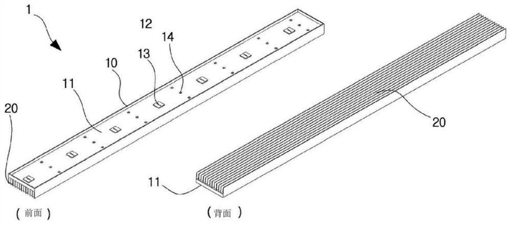
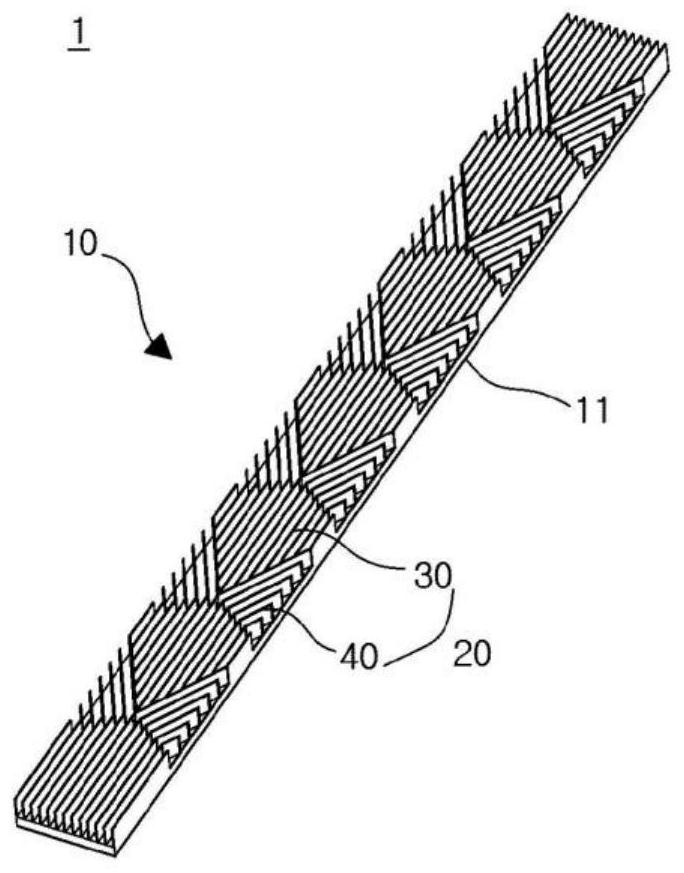
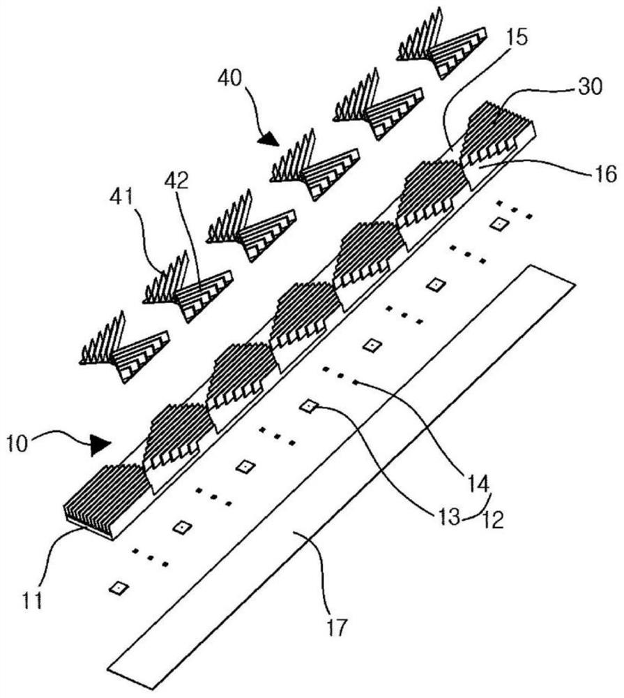
The present invention relates to a heat-radiating mechanism for an antenna device. Particularly, the heat-radiating mechanism comprises multiple communication elements for generating predetermined heat during electrically operating; a heat-radiating combined case having one surface on which the multiple communication elements are placed and the other surface on which multiple heat-radiating ribs are integrally formed; and an antenna board on which the multiple communication elements placed on the one surface of the heat-radiating combined case are mounted, wherein the multiple heat-radiating ribs are formed such that an ascending air current formed by heat relatively radiated from a lower portion of the heat-radiating combined case is discharged slantly upward and toward the left and rightof the width direction of the heat-radiating combined case in a relative upper portion thereof. Therefore, the heat-radiating mechanism provides an advantage of improving a heat-radiating performanceof the antenna device.

Description

technical field [0001] The present invention relates to a cooling device for an antenna device (COOLING DEVICE FOR ANTENNA APPARATUS). More specifically, it relates to a cooling device for an antenna device that can be formed at the lower end of a heat dissipation housing that is formed to be long in the vertical direction. The effect of updrafts is minimized for even cooling performance. Background technique [0002] Distributed antenna system (distributed antenna system) is an example of a relay system for relaying communication between base stations and user terminals, and is used to expand the service coverage of base stations so as to provide mobile communication services to indoor Or the shadow area that must be generated in the outdoor (outdoor). [0003] In the distributed antenna system, based on the downlink path, the base station receives the base station signal from the base station, performs signal processing such as amplification, and then transmits the signal...

Claims


Application Information

Patent Timeline
Patent Type & Authority Applications(China)
IPC IPC(8): H01Q1/02
CPCH01Q1/02H01Q1/246H01Q1/44
Inventor 俞昌佑朴敏植梁准佑
Owner KMW INC
Learn More