Device and method for aligning position of optical element in direction of optical axis

A technology of optical components and optical axis direction, which is applied in the field of optical measurement and can solve problems such as the inability to achieve the alignment of the measured optical components.

Inactive Publication Date: 2013-10-02
INST OF OPTICS & ELECTRONICS - CHINESE ACAD OF SCI
View PDF4 Cites 21 Cited by
  • Summary
  • Abstract
  • Description
  • Claims
  • Application Information

AI Technical Summary

Problems solved by technology

However, this method can only achieve the alignment of the CGH component it

Method used


Image

  • Device and method for aligning position of optical element in direction of optical axis
  • Device and method for aligning position of optical element in direction of optical axis
  • Device and method for aligning position of optical element in direction of optical axis

Examples


Example Embodiment

[0028] In order to make the objectives, technical solutions, and advantages of the present invention clearer, the following further describes the present invention in detail in conjunction with specific embodiments and with reference to the accompanying drawings.
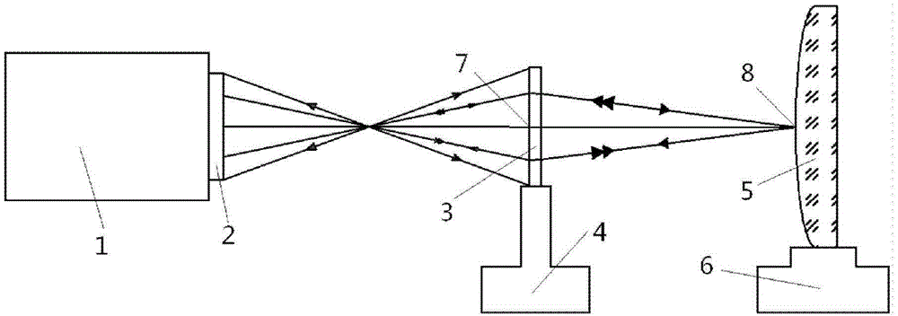
[0029] First combine Figure 1-Figure 4 To illustrate the device of the present invention for aligning the position of the optical element in the optical axis direction, the device includes: an interferometer 1, a standard lens 2, a computational hologram image 3 , Small five-dimensional adjustment frame 4, tested optical element 5, large five-dimensional adjustment frame 6, placed in sequence on the optical axis of the center line of the beam output by the interferometer 1, the standard lens 2, the computed hologram image 3 And optical element 5 under test, which will be computed holographic image 3 Fix it on the small five-dimensional adjustment frame 4, and fix the tested optical element 5 on the large five-dimensi...


PUM


Abstract

The invention discloses a device and a method for aligning a position of an optical element in a direction of an optical axis. The device comprises a normal lens, a computed hologram and the to-be-measured optical element which are sequentially placed in an optical axis of an output beam of an interferometer, wherein the computed hologram is fixed on a small five-dimensional adjustment rack; the to-be-measured optical element is fixed on a large five-dimensional adjustment rack; the computed hologram is placed in a design position behind a focus of the normal lens; a beam from the interior of the interferometer passes through the normal lens and emits to the computed hologram to allow a divergent spherical wave front to become a convergent spherical wave front; and a convergent focus is formed in the position in the direction of the optical axis of the to-be-measured optical element. The convergent spherical wave front returns along a symmetrical light path position when being irradiated onto the to-be-measured optical element, so that the convergent spherical wave front and a reference wave front in the interferometer form an interference fringe, and by monitoring the interference fringe, and adjusting the large five-dimensional adjustment rack, the position of the to-be-measured optical element in the direction of the optical axis is controlled at a wavelength order.

Description

technical field [0001] The invention belongs to the technical field of optical measurement, and in particular relates to a method for aligning the position of a measured optical element in the direction of an optical axis. Background technique [0002] In the detection of some optical components, such as the Hindle ball inspection secondary mirror, the alignment accuracy of the optical axis direction of the tested optical component has a great influence on the accuracy of the test results, so the appropriate alignment method is used to realize the measured optical component in the The precise alignment of the optical axis direction is particularly important in the inspection process. The spatial position of the measured optical element is monitored by using interference fringes, and its alignment accuracy can reach the order of wavelength. [0003] Rene Zehnder et al. from Arizona (Rene Zehnder, James H. Burge, Chunyu Zhao. "Use of computer generated holograms for alignment...

Claims


Application Information

Patent Timeline
IPC IPC(8): G01B11/27
Inventor 李世杰陈强闫锋涛范斌万勇建侯溪
Owner INST OF OPTICS & ELECTRONICS - CHINESE ACAD OF SCI
Why Eureka
Try Eureka