Automatic real-time measurement device for bending angle of bending machine

A bending angle and measuring device technology, applied in measuring devices, instruments, etc., can solve the problems of flexible deformation of steel wires and inability to transmit accurately, and achieve the effect of accurate measurement angle, precise transmission and simple device

Active Publication Date: 2013-10-02
南京埃斯顿软件技术有限公司
View PDF5 Cites 3 Cited by
  • Summary
  • Abstract
  • Description
  • Claims
  • Application Information

AI Technical Summary

Problems solved by technology

[0003] The technical problem to be solved by the present invention is to solve the problems of flexible deformation of the steel wire in the bending angle measuring device in the prior art, incapability of precise transmission and the need for additional mechanisms to return it to the original state, etc.

Method used


Image

  • Automatic real-time measurement device for bending angle of bending machine
  • Automatic real-time measurement device for bending angle of bending machine
  • Automatic real-time measurement device for bending angle of bending machine

Examples


Embodiment Construction

[0021] To make the content of the present invention more obvious and understandable, the following is attached Figure 1-Figure 6 And the specific implementation is further described.

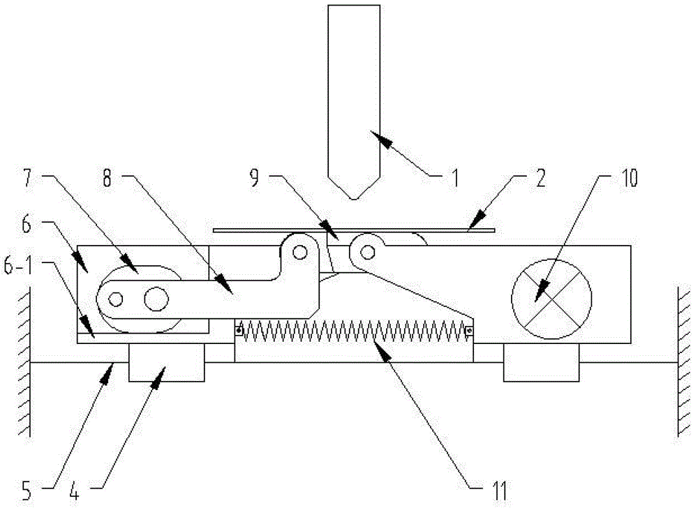
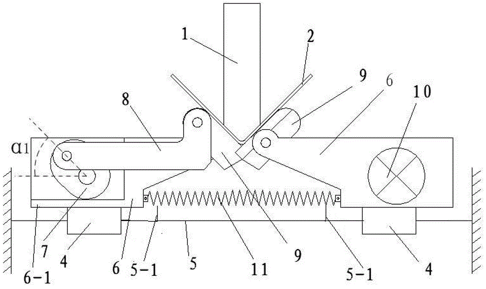
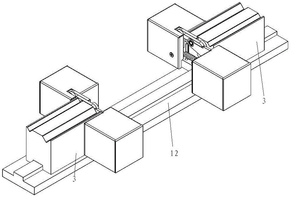
[0022] The bending angle measuring device of the present invention includes an upper die 1, a left half, a right half, a guide rod 5, a tension spring 11, and a base ( figure 1 Not shown in), workpiece 2; such as figure 1 As shown, figure 1 It is a schematic diagram of the initial state of the bending angle measuring device. Base ( figure 1 Not shown in the middle) is fixed on the base 12, and the guide rod 5 is fixed on the base ( figure 1 Not shown in the middle) top; the left half and the right half are fixed on the guide rod 5; the tension spring 11 connects the left half and the right half.

[0023] In the present invention, the left half and the right half have the same structure. Both the left half and the right half include a slider 4, an angle feedback element bracket 6, an angle feedback ...


PUM


Abstract

The invention discloses an automatic real-time measurement device for a bending angle of a bending machine and aims to solve the technical problems of steel wire flexible deformation, inaccurate transmission and the necessity of extra mechanism for backing to an initial state, in case of a conventional bending angle measurement device in the prior art. The technical scheme adopted is that the device provided by the invention comprises an upper die, a lower die and a workpiece, and further comprises a base and at least one bending angle measurement device body on the base, wherein the bending angle measurement device bodies and the lower die are fixed on the base; the bending angle measurement device bodies are positioned between the lower dies. The measurement device body, in the initial state, comprises a saddle fixed on the base, a guide rod fixed on the saddle, a left half part and a right half part both arranged on the guide rod in a sliding manner, and a tension spring connecting the left half part and the right half part. The device provided by the invention has the advantages that a link mechanism is adopted for accurate transmission, and self-return under the action of gravity is realized; and the bending angle of the overall workpiece is measured in a way of measuring the bending angles of two sides of the bended piece at the same time. Therefore, the automatic measurement device is simple, accurate in transmission, and easy to realize.

Description

Technical field [0001] The invention relates to a real-time automatic measuring device for bending angle of a bending machine, in particular to a real-time automatic measuring device for bending angle of a bending machine used on a bending machine for bending plate-shaped metal materials. Background technique [0002] Bending machine is a kind of equipment used to bend plate-shaped materials. The bending principle is to place the workpiece on the plane of the lower mold. When the upper mold presses the lower mold, the workpiece forms a bend under the action of the pressure and the upper and lower molds. Bend angle. When bending workpieces (such as sheet metal parts), how to accurately control the bending angle of the workpiece is the performance of the bending machine that both manufacturers and applications of bending machine must pay attention to. At present, there are a variety of bending angle measurement methods for bending machines. Some of these methods solve the problem ...

Claims


Application Information

Patent Timeline
Patent Type & Authority Applications(China)
IPC IPC(8): G01B21/22
Inventor 黄沁刘丽琼吴波
Owner 南京埃斯顿软件技术有限公司
Why Eureka
Try Eureka