Acoustic detection system for cast iron material defects

A material defect and detection system technology, applied in the direction of using sonic/ultrasonic/infrasonic waves to analyze solids, can solve problems such as alignment difficulties, the detection system cannot determine whether there are defects or slag inclusions in the detected position, and avoid economic losses. Effect

Active Publication Date: 2013-10-02
CHINA SPECIAL EQUIP INSPECTION & RES INST +1
View PDF5 Cites 2 Cited by
  • Summary
  • Abstract
  • Description
  • Claims
  • Application Information

AI Technical Summary

Problems solved by technology

However, the inherent characteristics of cast iron materials and the particularity of the casting process make it inevitable that there will be defects in cast iron components and equipment.
Among them, the reflective detection needs to be scanned point by point, which is time-consuming and laborious; while the scanning probe and the excitation probe of the transmissive scanning are located on both sides of the surface to be inspected, and the alignment between the two is difficult
[0004] More importantly, when the existing acoustic detection system detects metal defects, it mostly uses a hand-push detection ruler to determine the pre-movement position of the probe, which makes the determination of the probe position inaccurate; The inspected area is constantly marked on the test board, which is time-consuming and laborious; and the existing inspection system cannot determine whether there is a defect in the inspected position in real time during the inspection, and it often needs to be processed according to the later data.

Method used


Image

  • Acoustic detection system for cast iron material defects
  • Acoustic detection system for cast iron material defects

Examples


Embodiment Construction

[0020] The specific implementation manners of the present invention will be further described in detail below in conjunction with the accompanying drawings and embodiments. The following examples are used to illustrate the present invention, but are not intended to limit the scope of the present invention.

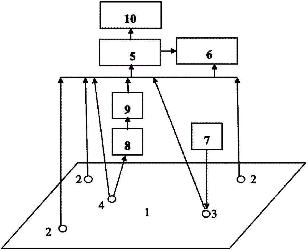
[0021] figure 1 It shows the configuration diagram of the acoustic detection system for cast iron material defects in this embodiment. Referring to the figure, it mainly includes an excitation module, a receiving module, a calibration module, a calculation module, a display module and a storage module; among them,

[0022] The excitation module includes an excitation probe 3 and a pulse signal generator 7 connected thereto. The pulse signal generator 7 is used to generate a pulse signal for the excitation probe 3. The excitation probe 3 is detachably fixed on the cast iron plate 1 to be tested for Transmitting an ultrasonic excitation pulse signal to the cast iron plate ...


PUM


Abstract

The invention relates to an acoustic detection system for cast iron material defects. The acoustic detection system comprises an excitation module, a reception module, a calibration module, a calculation module, a display module and a storage module. The calibration module is used for determining the coordinate system of the surface of a plate to be detected. The calculation module is used for calculating an amplitude of a scanning probe at a real-time position, comparing the amplitude with a standard attenuation amplitude corresponding to the position, and calculating a difference percentage of the two amplitudes. The display module is used for displaying the difference percentage, a given permissible difference percentage threshold value and the coordinate system determined by the calibration module, and displaying the surface of the cast iron plate to be detected, real-time position of an excitation probe, and real-time position of the scanning probe in the coordinate system. Detection results can be visually, rapidly and accurately obtained by the acoustic detection system provided by the invention.

Description

technical field [0001] The invention relates to the technical field of non-destructive testing, in particular to an acoustic testing system for defects in cast iron materials. Background technique [0002] Cast iron materials have been widely used in urban gas pipelines, paper drying cylinders, automobiles and other equipment or components due to their excellent castability, wear resistance and shock absorption, high yield and low cost. However, the inherent characteristics of cast iron materials and the particularity of the casting process make it inevitable that there will be defects in cast iron components and equipment. Common defects include: porosity, slag inclusion, cold shut, shrinkage cavity and porosity, cracks, etc. At present, the non-destructive testing techniques for internal defects of cast iron materials mainly include radiographic testing and pulse reflection ultrasonic testing. Radiographic testing can detect manufacturing defects such as porosity, porosit...

Claims


Application Information

Patent Timeline
Patent Type & Authority Applications(China)
IPC IPC(8): G01N29/11
Inventor 沈功田李丽菲吴占稳张峥
Owner CHINA SPECIAL EQUIP INSPECTION & RES INST
Why Eureka
Try Eureka