A method suitable for portable radio monitoring all-in-one machine to identify antenna

A technology for radio monitoring and identification of antennas, applied in the direction of measuring electricity, measuring devices, measuring electrical variables, etc., can solve the problems of inability to detect and analyze antennas, high failure rate, inconvenient to carry and use, etc., to achieve the convenience of monitoring antenna types , the effect of low manufacturing cost and simple structure

Active Publication Date: 2015-08-26
CHENG DU DIAN ZHEN TECH
View PDF4 Cites 0 Cited by
  • Summary
  • Abstract
  • Description
  • Claims
  • Application Information

AI Technical Summary

Problems solved by technology

[0004] Before the appearance of the portable radio monitoring all-in-one machine that the applicant applied for at the same time, the existing portable radio monitoring system was mainly composed of several major components such as a signal processing unit, a receiver, an electronic compass and an antenna; the radio signal induced by the antenna was connected to the receiver, The intermediate frequency signal of the receiver is processed by FFT and then output to the signal processing unit. The signal processing unit outputs the parameters of the signal to the display for display after data calculation according to the direction indication of the electronic compass; The problems of split-type radio monitoring equipment composed of several major components such as compass and antenna include: 1. The radio monitoring equipment is formed by split-type combination, which is particularly inconvenient to carry and use; 2. A large number of connectors are required between multiple components, resulting in The concealment of radio monitoring equipment is poor, and the failure rate of each component is high; 3. The lack of antenna monitoring function module makes it impossible to detect and analyze the antenna for immediate use; Receiving terminal for information transmission
The disadvantage of the product of this patent is that the user also needs to wear information processing devices, antennas, electronic compass and other equipment to form a radio monitoring system that can monitor radio signals; however, since the direction finding host and information processing devices are separate When performing radio monitoring, the user needs to hang or carry it on the body respectively, and then carry out radio monitoring through the hand-held antenna. Such a structure is not only complicated, but also has a single function, poor operation concealment, and portability. Poor; and does not have the identification function of directional antenna

Method used


Image

  • A method suitable for portable radio monitoring all-in-one machine to identify antenna
  • A method suitable for portable radio monitoring all-in-one machine to identify antenna
  • A method suitable for portable radio monitoring all-in-one machine to identify antenna

Examples


Embodiment 1

[0037] A method for identifying antennas suitable for a portable radio monitoring integrated machine, characterized in that it includes a directional antenna identification step, and the directional antenna identification step includes:

[0038] A. Scan the chassis connector to determine whether there is a directional antenna connected to the chassis connector through the antenna connector. If there is no directional antenna connected, continue scanning;

[0039] B. If there is a directional antenna connected, when the signal processing unit contacts one of the two contact points on the casing connector through the encoding board in the antenna connector connection cavity, the value of the antenna installation direction of the horizontally installed antenna is read ; When the encoding board is in contact with another contact point, the antenna installation direction value of the vertically installed antenna is read; the signal processing unit reads the polarization direction of...

Embodiment 2

[0048] A method for identifying antennas suitable for a portable radio monitoring integrated machine, characterized in that it includes a directional antenna identification step, and the directional antenna identification step includes:

[0049] A. Scan the chassis connector to determine whether there is a directional antenna connected to the chassis connector through the antenna connector. If there is no directional antenna connected, continue scanning;

[0050] B. If there is a directional antenna connected, when the signal processing unit contacts one of the two contact points on the casing connector through the encoding board in the antenna connector connection cavity, the value of the antenna installation direction of the horizontally installed antenna is read ; When the encoding board is in contact with another contact point, the antenna installation direction value of the vertically installed antenna is read; the signal processing unit reads the polarization direction of...

Embodiment 3

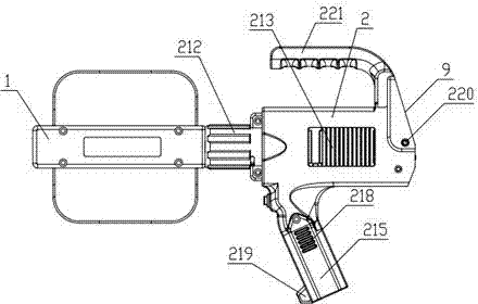
[0059] The difference from Embodiments 1 and 2 is that: a method applicable to portable radio monitoring all-in-one machine for identifying antennas also includes a directional antenna installation step, the directional antenna installation step is to insert the antenna connector with the coding board into the portable radio After the rotary locking sleeve on the casing of the monitoring all-in-one machine is connected to the casing connector with a contact point in the rotary locking sleeve, the rotating locking sleeve is rotated to fix the directional antenna on the portable radio monitoring all-in-one machine to form a portable radio monitoring system.

[0060] In the present invention, the value of N is 4, and the nodes are connected by diodes to form a 4×4 matrix, which can generate 16 kinds of codes; such a structure allows users to use 16 different types of directional antennas when operating in the field identification, radio monitoring after identification.

[0061] ...


PUM


Abstract

The invention discloses an antenna identification method applicable to a portable radio monitoring one-body machine. The method comprises directional antenna identification steps that: A, a scanning casing connector determines whether connection of a directional antenna and the casing connector through an antenna connector occurs, if access of the directional antenna does not occur, scanning continues; B, if access of the directional antenna occurs, when a signal processing unit contacts with one of two contacts on the casing connector through a coding board in an antenna connector connection chamber, an antenna mounting direction value of a horizontally-mounted antenna is read; when the other coding board contacts with the other contact of the two contacts, an antenna mounting direction value of a vertically-mounted antenna is read; the signal processing unit reads a polarized direction of the directional antenna utilized by a present system through reading the antenna mounting direction values; and C, the signal processing unit further reads an antenna coding value through the contacts and the coding board; the signal processing unit reads a type of the directional antenna utilized by the present system through the antenna coding value.

Description

Technical field [0001] The present invention involves radio monitoring methods, especially a method that is suitable for identifying the antenna type for portable radio monitoring all -in -one. Background technique [0002] At present, the vast majority of portable receiving antenna has no antenna recognition function, such as HE200, HE300 and other handheld antenna series produced by R & S in Germany; and the IDA-3106 interference directional analyzer of Germany's NARDA company, the antenna, Start with a simple antenna type recognition function. By the raised parts on the antenna plug, the corresponding encoding switch in the antenna socket on the shell to identify the installation position and type of antenna; it is also currently only availableThe antenna polarization recognition function handheld antenna; but due to the narrow space inside the antenna socket, the structure of the mechanical switch contact is complicated, and the type of antenna recognition is subject to the n...

Claims


Application Information

Patent Timeline
Patent Type & Authority Patents(China)
IPC IPC(8): G01R29/00G01R29/08G01R31/00
Inventor 邱承跃白宇军
Owner CHENG DU DIAN ZHEN TECH
Why Eureka
Try Eureka