Burglary-resisting monitoring and positioning method for armored cable

A technology of armored cable and armored sheath, which is applied in the field of anti-theft detection and positioning of armored cables, which can solve the problems of cable electrical parameter changes, influence, and low induced voltage, and achieve the effect of ensuring safe operation

Active Publication Date: 2013-10-02
康威通信技术股份有限公司
View PDF11 Cites 11 Cited by
  • Summary
  • Abstract
  • Description
  • Claims
  • Application Information

AI Technical Summary

Problems solved by technology

[0004] 1. For armored anti-theft products on the market, when the armored cable is cut or stolen, the alarm device will emit an audible or optical alarm signal. However, when some thieves steal, they generally do not cut off the entire cable and steal it. Instead, steal the shielding layer under the armored layer. Since the induced voltage on the armored layer and the shielded layer is very low, the conductor layer, refractory layer and insulating layer of the armored cable will not be broken, which will not affect the normal power supply. , so it is difficult to detect the armored cable being stolen, resulting in poor anti-theft effect
[0005] 2. Patent No. 201220561755.5 "Armored cable online anti-theft and anti-external damage monitoring and alarm device", according to its technical proposal and the description of the claims, this patent can only realize the monitoring of whether the armored cable closed circuit is damaged. It can call the police when it is damaged, and the technical plan, claims and implementation cases do not mention that the damage point can be located, so from a technical point of view, the patent cannot locate the damage point of the armored cable
This method will cause the electrical parameters of the cable to change, which will have an unpredictable impact on the safety and life of the cable, which is not conducive to the safe operation of the cable.

Method used


Image

  • Burglary-resisting monitoring and positioning method for armored cable
  • Burglary-resisting monitoring and positioning method for armored cable

Examples


Embodiment Construction

[0030] The present invention will be further described below in conjunction with the accompanying drawings and embodiments.

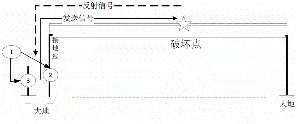
[0031] Such as figure 1 As shown, both ends of the armored sheath of the power armored cable are grounded, and one grounding end of the armored sheath is selected. The armored sheath anti-theft monitoring terminal 1 sends a signal of a specific frequency to the earth through the ground stake 3. The armored cable The sheath is coupled to the signal through the ground so that the signal travels in the direction of the armor sheath. Similarly, the armored sheath anti-theft monitoring terminal 1 receives the specific frequency signal reflected in the armored sheath through the receiving transformer 2. When the armored sheath of the armored cable is damaged, the armored sheath will have a breakpoint or impedance In the case of an increase, the reflected signal can be detected at this time. By detecting the time difference between the sent signal and the ref...


PUM


Abstract

The invention particularly discloses a burglary-resisting monitoring and positioning method for an armored cable, which comprises the following steps: 1, selecting a grounding point at one end of a cover layer of the armored cable to be monitored to serve as a testing point; 2, piling a pile at the place near the grounding point selected in the step 1, and sleeving a transformer on a grounding wire of the cover layer of the armored cable; 3, sending signal at specific frequency by an armored cover layer burglary-resisting monitor terminal, and coupling the signal into the armored cover layer through the grounding pile; 4, receiving the specific frequency signal and reflected signal of the armored cover layer by the armored cover layer burglary-resisting monitor terminal through the transformer; 5, in case the armored cover layer is damaged, breaking point occurs or impedance is increased, detecting the reflected signal at the signal emission point, and calculating the distance between the break point and the signal emission point through detecting the time difference between the transmission signal and reflected signal.

Description

technical field [0001] The invention relates to the field of cable anti-theft technology, in particular to an armored cable anti-theft detection and positioning method. Background technique [0002] With the rapid development of our country's economy, the city's electricity consumption is increasing day by day, and the safety requirements for the power grid and its design are also increasing day by day. For the important facilities of the power grid, armored cables, due to man-made theft and external construction, frequent damage accidents have caused huge losses to work, production and daily life. Therefore, the monitoring of armored cables is imperative. [0003] At present, there are many armored cable anti-theft products on the market, all of which have problems of varying degrees: [0004] 1. For armored anti-theft products on the market, when the armored cable is cut or stolen, the alarm device will emit an audible or optical alarm signal. However, when some thieves ...

Claims


Application Information

Patent Timeline
Patent Type & Authority Applications(China)
IPC IPC(8): G08B13/12G01R31/08
Inventor 杨震威吴海滨
Owner 康威通信技术股份有限公司
Why Eureka
Try Eureka