Power source reverse connection protection circuit

A technology of protection circuit and power reverse connection, applied in emergency protection circuit devices, circuit devices, emergency protection devices with automatic disconnection, etc., can solve the problems of prolonging development time, troublesome replacement, increasing development cost, etc. The warning is obvious, the structure is simple, and the effect of protecting the power supply

Inactive Publication Date: 2013-10-02
XIDIAN UNIV
View PDF3 Cites 2 Cited by
  • Summary
  • Abstract
  • Description
  • Claims
  • Application Information

AI Technical Summary

Problems solved by technology

In the process of frequently connecting and removing the power supply, it is inevitable that the power line will be reversed, that is, the positive and negative poles of the power line will be reversed by mistake. If the circuit does not have sufficient protection measures, the subsequent circuit will be burned Or the power supply, or the power supply and the subsequent circuit are burned at the same time, resulting in waste of devices and time, prolonging development time, increasing development costs, and sometimes even causing safety hazards
[0003] The commonly used methods to prevent reverse connection of power supply are as follows: 1. Anti-reverse connector; this method is the simplest and most commonly used method with the lowest cost, but it is generally used as a finished product, because this kind of connector bites Difficult to separate, it is inconvenient for the development site that needs to be split frequently; 2. The reverse connection diode of the power input port; this method is often used in development, but this protection circuit can only protect the subsequent circuit. The design idea is to choose to sacrifice the power supply, there is no obvious alarm device, and it is easy to burn the power supply; 3. The fuse; although it can protect the circuit to a large extent, it is troublesome to replace, and for sensitive devices, the protection effect is not obvious; 4. Automatic Protection circuit; this kind of circuit is generally designed at the power supply end to cut off the power supply output in case of short-circuit prevention, and is generally used as a self-protection circuit for the circuit
[0004] These circuit protection methods each have their own application fields, but none of them can protect the front-end and back-end circuits very well.

Method used


Image

  • Power source reverse connection protection circuit
  • Power source reverse connection protection circuit

Examples


Embodiment Construction

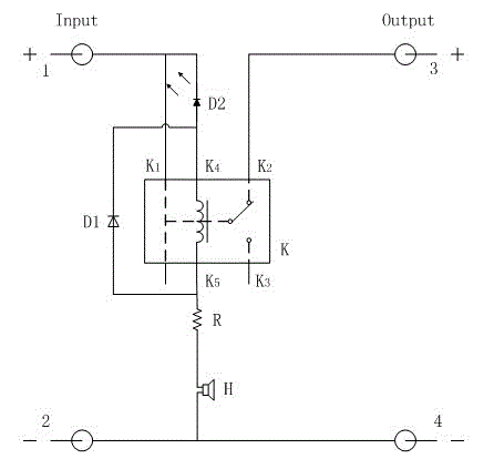
[0016] Such as figure 1 Shown is a circuit diagram of a power supply reverse connection protection circuit of the present invention, including: SPDT relay K, protection diode D1, light emitting diode D2, resistor R, buzzer H; wherein pin K1 of SPDT relay K is connected to The positive input terminal 1 of the power supply is connected, the pin K2 is connected with the positive output terminal 3 of the power supply, the first control pin K4 is connected with the positive pole of the light-emitting diode D2, the second control pin K5 is connected with one end of the resistor R; the resistor R The other end of the LED is connected to the negative pole of the buzzer H; the positive pole of the buzzer H is connected to the negative input terminal 2 of the power supply; the negative pole of the light emitting diode D2 is connected to the positive input terminal 1 of the power supply; the negative pole of the protection diode D1 is connected to the single pole double throw relay The f...


PUM


Abstract

The invention relates to a power source reverse connection protection circuit, which is composed of a single-pole double-throw relay K, a protection diode D1, a light emitting diode D2, a resistor R and a hummer H; when the circuit is in normal operation, that is, no power source reverse connection fault exists, a positive output end (3) of a power source is directly connected with a positive input end (1) of the power source; when the power source is in reverse connection, the single-pole double-throw relay K works to cut off the following circuits and lightens the light emitting diode D2, and meanwhile, the hummer H sounds to prompt the power source reverse connection fault for the user. The circuit is simple in structure, low in cost and obvious in warning of reverse connection fault, not only can protect the following circuits from being burnt out due to power source reverse connection, but also can efficiently restrain the current, so the function of power source protection can be achieved.

Description

technical field [0001] The invention belongs to the technical field of circuit protection and relates to a power reverse connection protection circuit. Background technique [0002] In the development process of all electronic equipment or products, the power supply is an essential component, and it is also the most frequently used component. Especially in the development and testing stage, frequent power on and off is an essential process. In the process of frequently connecting and removing the power supply, it is inevitable that the power line will be reversed, that is, the positive and negative poles of the power line will be reversed by mistake. If the circuit does not have sufficient protection measures, the subsequent circuit will be burned Or the power supply, or the power supply and the subsequent circuit are burned at the same time, resulting in waste of devices and time, prolonging development time, increasing development costs, and sometimes even causing safety h...

Claims


Application Information

Patent Timeline
Patent Type & Authority Applications(China)
IPC IPC(8): H02H11/00H02H3/04
Inventor 李平张庞源王新怀李蕊石强史小卫
Owner XIDIAN UNIV
Why Eureka
Try Eureka