Method for preparing composite flying plate in laser indirect impact micro-forming

A micro-forming and flyer technology, applied in laser welding equipment, welding equipment, chemical instruments and methods, etc., can solve the problem of low laser impact flyer forming ability and forming quality, low laser energy coupling efficiency, and low flyer speed. and other problems, to achieve the effect of high laser energy utilization rate, low preparation cost and high preparation efficiency

Inactive Publication Date: 2013-10-09
JIANGSU UNIV
View PDF4 Cites 5 Cited by
  • Summary
  • Abstract
  • Description
  • Claims
  • Application Information

AI Technical Summary

Problems solved by technology

[0005] In view of the problems existing in the laser-driven flyer forming process in the prior art, the forming ability of the laser impact flyer is poor due to the weak bonding force between the flyer and the substrate, low laser energy coupling efficiency, low flyer speed and poor integrity. To solve the problem of low forming quality, a method for preparing composite flyers in laser indirect impact microforming was proposed

Method used


Image

  • Method for preparing composite flying plate in laser indirect impact micro-forming
  • Method for preparing composite flying plate in laser indirect impact micro-forming
  • Method for preparing composite flying plate in laser indirect impact micro-forming

Examples


Embodiment Construction

[0025] The present invention will be described in further detail below in conjunction with the accompanying drawings.

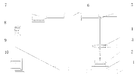
[0026] figure 1 It is a schematic diagram of a laser-driven flyer indirect micro-forming device using the composite flyer of the present invention. The computer 10 controls the laser controller 8, and the laser controller 8 can adjust the pulse laser parameters emitted by the nanosecond laser 7. The pulsed laser light emitted by the nanosecond laser is finally transmitted to the positioning shaping device 3 through the laser shaper 6 , the mirror 5 and the focusing lens 4 . The positioning forming device 3 is installed on the three-dimensional mobile platform 2 . The three-dimensional mobile platform 2 is installed on the L-shaped base 1, and the displacement adjustment of the three-dimensional mobile platform 2 is regulated by the three-dimensional mobile platform controller 9 controlled by the computer 10.

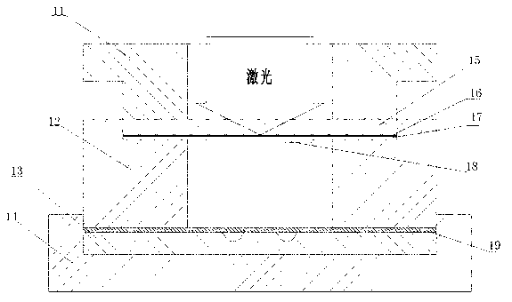
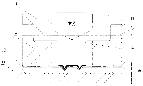
[0027] figure 2 It is a structural schematic...


PUM

PropertyMeasurementUnit
diameteraaaaaaaaaa
reflectanceaaaaaaaaaa

Abstract

The invention discloses a method for preparing a composite flying plate in laser indirect impact micro-forming. K9 glass is selected to serve as a sputtering substrate; titanium is selected to serve as a first sputtering target, aluminum is selected to serve as a second sputtering target, a Ti-Al composite film layer is obtained through magnetron sputtering for twice, and the Ti-Al composite film layer serves as an absorbing/ablation layer of a flying plate driven by lasers; metal foil or non-metal foil is adhered to the Ti-Al composite film layer; pressure is exerted between the flying plate and the Ti-Al composite film layer and the flying plate and the Ti-Al composite film layer are placed in a constant temperature device; the flying plate and the Ti-Al composite film layer are taken out from the constant temperature device so that the composite flying plate can be formed. The composite flying plate prepared through the method is high in laser energy use rate and good in completeness. The flying plate good in completeness can be obtained and forming performance is improved. The composite flying plates with different properties can be obtained through the adjustment of preparing parameters. The method for preparing the composite flying plate in laser indirect impact micro-forming is convenient to use, reliable, simple in technology, high in preparing efficiency, low in preparing cost and capable of being used in large-scale production and application in industry.

Description

technical field [0001] The invention relates to a method for preparing composite flyers in laser indirect impact micro-forming, and belongs to the technical field of advanced laser manufacturing. Background technique [0002] Laser-driven flyer forming technology is a new type of high-pressure and high-strain rate forming technology, that is, the laser-driven flyer loading method replaces the direct laser impact, and the laser energy is converted into the kinetic energy of the flyer. The carrier, after flying for a certain distance, collides with the workpiece material, and high-pressure shock waves are generated on the collision interface to cause ultra-fast plastic deformation of the material in the micro-mold, thereby realizing the precise forming of the workpiece in the micro-mold. [0003] Laser-driven flyer forming technology can realize the micro-forming of complex devices that are difficult or impossible to form by conventional methods. Among them, the quality of th...

Claims


Application Information

Patent Timeline
Patent Type & Authority Applications(China)
IPC IPC(8): B23K26/42C23C14/35C23C14/18B32B37/12B32B37/10
Inventor 王霄袁耀强沈宗宝顾春兴张强陆萌萌刘会霞
Owner JIANGSU UNIV
Why Eureka
Try Eureka